
Method, device and system for controlling a sound image in an audio zone

a technology of sound image and audio zone, applied in the direction of transducer circuit, electrical transducer, loudspeaker spatial/constructional arrangement, etc., can solve the problem of sound from a second audio zone being transported to, and thus heard in, a first zone, and achieve the effect of reducing the bass volume of the adjusting loudspeaker, minimizing the required adjustment, and increasing the speaker volum

Active Publication Date: 2017-11-21
AXIS
View PDF15 Cites 0 Cited by
  • Summary
  • Abstract
  • Description
  • Claims
  • Application Information

AI Technical Summary

Benefits of technology

[0008]Since the audio system may automatically adjust the audio zones, a user of the system can be confident in that it is acceptable in view of the sound image of other audio zones to raise the volume level of a loudspeaker in an audio zone. Thus, the method is advantageous also from a user perspective.
[0015]In one embodiment, the adjustment of the adjusting loudspeaker comprises decreasing the bass volume of the adjusting loudspeaker. Bass sound typically propagates long and may be the only affecting part of the sound in the adjusting audio zone. By decreasing only the bass volume, the speaker volume, and other sound parameters, may be left unadjusted thus minimizing the required adjustment.
[0016]In one embodiment, the adjusting audio zone has a plurality of loudspeakers located therein. The method of this embodiment may further comprise increasing the speaker volume of a further adjusting loudspeaker, being another of the one or more loudspeakers. By this embodiment, the provided sound in the adjusting audio zone may be optimized in view of minimizing the influence of the provided sound on the sound image of the controlling audio zone.

Problems solved by technology

When multiple audio zones are present in an audio system, there is a risk that sound from a second audio zone is transported to, and thus heard in, a first zone.

Method used


Image

  • Method, device and system for controlling a sound image in an audio zone
  • Method, device and system for controlling a sound image in an audio zone
  • Method, device and system for controlling a sound image in an audio zone

Examples


Embodiment Construction

[0037]The present invention will now be described more fully with reference to the accompanying drawings, in which currently preferred embodiments of the invention are shown. The invention may however be embodied in many different forms and should not be construed as limited to the embodiments set forth herein.

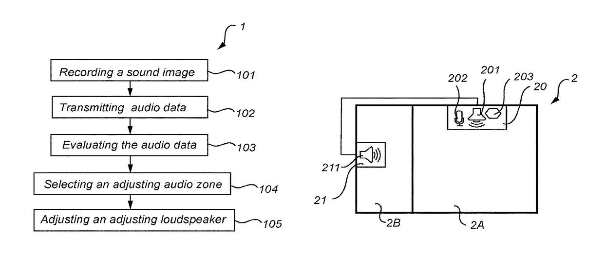
[0038]A method 1 for adjusting a sound image of an audio zone according to an embodiment of the invention is illustrated in FIG. 1. The audio zone is one of a plurality of audio zones which together form an audio system. Each audio zone comprises one or more loudspeakers arranged to provide audio to a corresponding audio zone. The purpose of the method 1 is to adjust the audio system for achieving a desired sound image in one of the audio zone which is referred to as the controlling audio zone.

[0039]The method 1 comprises recording 101 a sound image of the controlling audio zone. The sound image is recorded by a microphone unit which is located within the controlling audio zon...


PUM


Abstract

A method for adjusting an audio zone sound image in an audio system (2, 6, 7) comprising a plurality of audio zones (2A, 2B, 6A, 6B, 6C, 6D, 7A, 7B, 7C) is disclosed. Each audio zone has one or more loudspeakers (20, 21, 60, 61, 63, 64, 65, 66, 67, 68, 69, 70, 72, 73, 74, 75) located therein. The method comprises recording (101, 802) a sound image of a controlling audio zone; transmitting (102, 803) audio data corresponding to the recorded sound image to a controller; evaluating (103, 103a, 804) the transmitted audio data; selecting (104, 805) an adjusting audio zone, wherein the adjusting audio zone is other than the controlling audio zone; and adjusting (105, 105a, 105b, 807) an adjusting loudspeaker such that the sound image of the controlling audio zone is changed. An audio system (2, 6, 7) and a controlling loudspeaker are also disclosed.

Description

TECHNICAL FIELD[0001]The present invention relates to a method for adjusting a sound image in one of a plurality of audio zones in an audio system. The invention also relates to an audio system and a controlling loudspeaker.BACKGROUND OF THE INVENTION[0002]The use of audio systems having multiple audio zones has become increasingly common. Each audio zone comprises one or more loudspeakers for providing sound to the corresponding audio zone. Different audio zones may for example cover different rooms in a building. The audio system may be used for providing sound such as music, voice messages, sound signals, etc. Audio systems are also commonly used in homes today where one or more audio zones are provided in different rooms for playing music or radio. Two or more audio zones may be grouped in order to provide the same sound in multiple audio zones. Different audio zones may of course provide different sounds as well.[0003]When providing sound in an audio zone, it may be desired to ...

Claims


Application Information

Patent Timeline
Patent Type & Authority Patents(United States)
IPC IPC(8): H04R3/12H04R3/00H04R29/00
CPCH04R3/12H04R3/005H04R29/001H04R2430/01H04R2227/001H04R2227/005H04R2430/00H04R5/02H04S3/002H04S3/008H04R2227/003
Inventor HANSSON, NIKLASLINDELL, ARVID NIHLGARD
Owner AXIS
Learn More