Chair for relieving back pain

Active Publication Date: 2017-11-28
EEM
View PDF28 Cites 1 Cited by
  • Summary
  • Abstract
  • Description
  • Claims
  • Application Information

AI Technical Summary

Benefits of technology

[0005]The object of the invention is therefore to avoid the disadvantages of the prior art and, in particular, to create

Problems solved by technology

By predefining the backrest angle, a maximu

Method used


Image

  • Chair for relieving back pain
  • Chair for relieving back pain
  • Chair for relieving back pain

Examples


Embodiment Construction

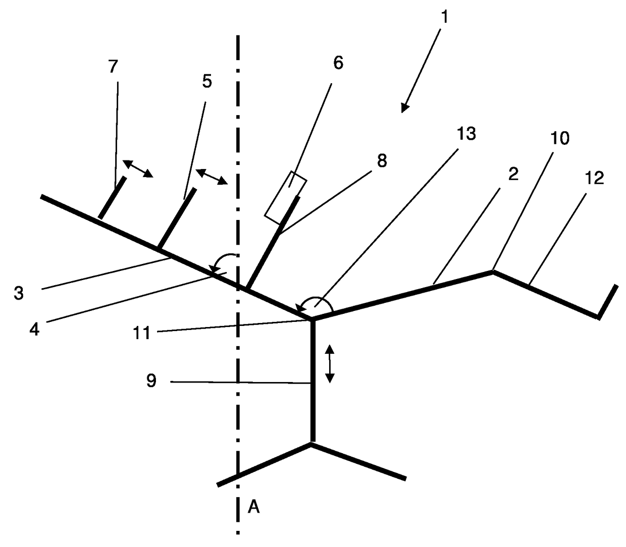
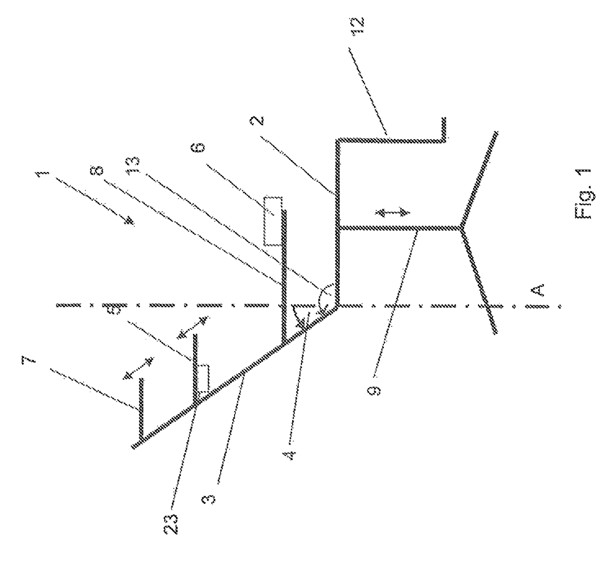
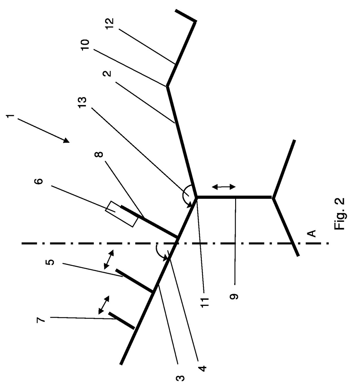
[0058]FIG. 1 shows a chair 1 according to the invention, with a seat surface 2 and with a backrest 3. The backrest angle 4 between the backrest 3 and a vertical A is designed to be adjustable. The seat surface 2 is horizontal here, i.e. oriented perpendicularly with respect to the vertical A. Moreover, the chair 1 comprises support elements 5 with an electric drive 23, which are formed on the backrest 3 and are adjustable in respect of a distance from the seat surface 2. The support elements 5 protrude from the backrest 3 in such a way that they are arranged on both sides of the upper body of a user, under the arms or armpits. It will be appreciated that the support elements 5 can also be designed in one piece as a single support element 5.

[0059]With the aid of operating element 6, a user can set the backrest angle 4 and a position of the support elements 5. Moreover, a headrest 7 is formed, which is likewise adjustable using the operating element 6. When adjusted in the direction o...


PUM


Abstract

A chair (1) for relieving back pain of a user, with a seat surface (2) and a backrest (3), wherein a backrest angle (4) between backrest (3) and seat surface (2) is adaptable. At least one support element (5) for supporting the upper body of the user, when the latter is in an intended sitting position, is arranged on the backrest (3), wherein the support element (5), in the intended sitting position, can preferably be arranged, or is arranged, under the armpits of the user. The support element (5) is designed in such a way, and arranged on the backrest in such a way, that it can be moved by the user in order to obtain a desired support of the upper body at a predefined backrest angle (4) while he is in the intended sitting position.

Description

FIELD OF THE INVENTION[0001]The invention relates to a chair for relieving back pain in accordance with the preamble of the independent claim.BACKGROUND OF THE INVENTION[0002]Chairs for improving wellbeing; for example massage chairs, are widely known.[0003]A comfort chair for relieving the vertebral column is known from DE 10 2009 030 390. The chair comprises mechanically adjustable armpit supports, which help relieve the vertebral column. Moreover, the backrest of the chair is designed to be tiltable. A disadvantage of such a design of the chair is that the height setting of the armpit support has to be predefined before use and cannot be adjusted independently by the user when he is in the sitting position. In addition, an effective extension force is closely coupled to the inclination of the backrest.[0004]A chair for relieving the vertebral column is known from U.S. Pat. No. 1,356,356. The chair has an armpit support and a headrest, which are adjustable independently of each ot...

Claims


Application Information

Patent Timeline
IPC IPC(8): A61H1/02A47C7/38A47C1/035A47C1/03
CPCA61H1/0292A47C1/03A47C1/035A47C7/38A61H1/0218A61H1/0229A61H2201/5061A61H2201/0149A61H2201/0176A61H2201/0207A61H2201/1664A61H2201/1676A47B83/02A47C1/0308
Inventor RUF, HANS
Owner EEM
Why Eureka
Try Eureka