
Vertical traction assembly and method

a technology of vertical traction and assembly, which is applied in the field of vertical traction assembly and method, can solve the problems of temporary and permanent disability of many people, inability to get lasting relief, and may even get worse, and achieve the effect of relieving pain and reducing inflammation

Inactive Publication Date: 2002-12-05
PERREGO DAVID
View PDF16 Cites 2 Cited by
  • Summary
  • Abstract
  • Description
  • Claims
  • Application Information

AI Technical Summary

Benefits of technology

[0011] The primary purpose of the invention is to provide a traction unit for decreasing inflammation and stress on specific, affected areas of a person's spine for those having severe back conditions and to relieve pain caused by inflammation by the various known disorders affecting the spine as noted above.
[0013] A further object of the invention is to provide a traction unit with a simple construction so that it takes up minimal floor space and may be easily used for applying about 40% of a person's weight to stretch the person's spine to relieve back pain.
[0015] Another object of the invention is to provide a traction assembly that reduces the amount of time a patient must spend in traction to gain spinal-centered pain relief.
[0017] The invention comprises a traction assembly that directs a focused traction force specifically to the area of maximal muscle strain and spasm along a patient's spine. This traction force decreases stress on affected areas of the spine and truly allows the affected muscles to relax and stretch thus reducing the inflammatory process that predominantly generates pain.
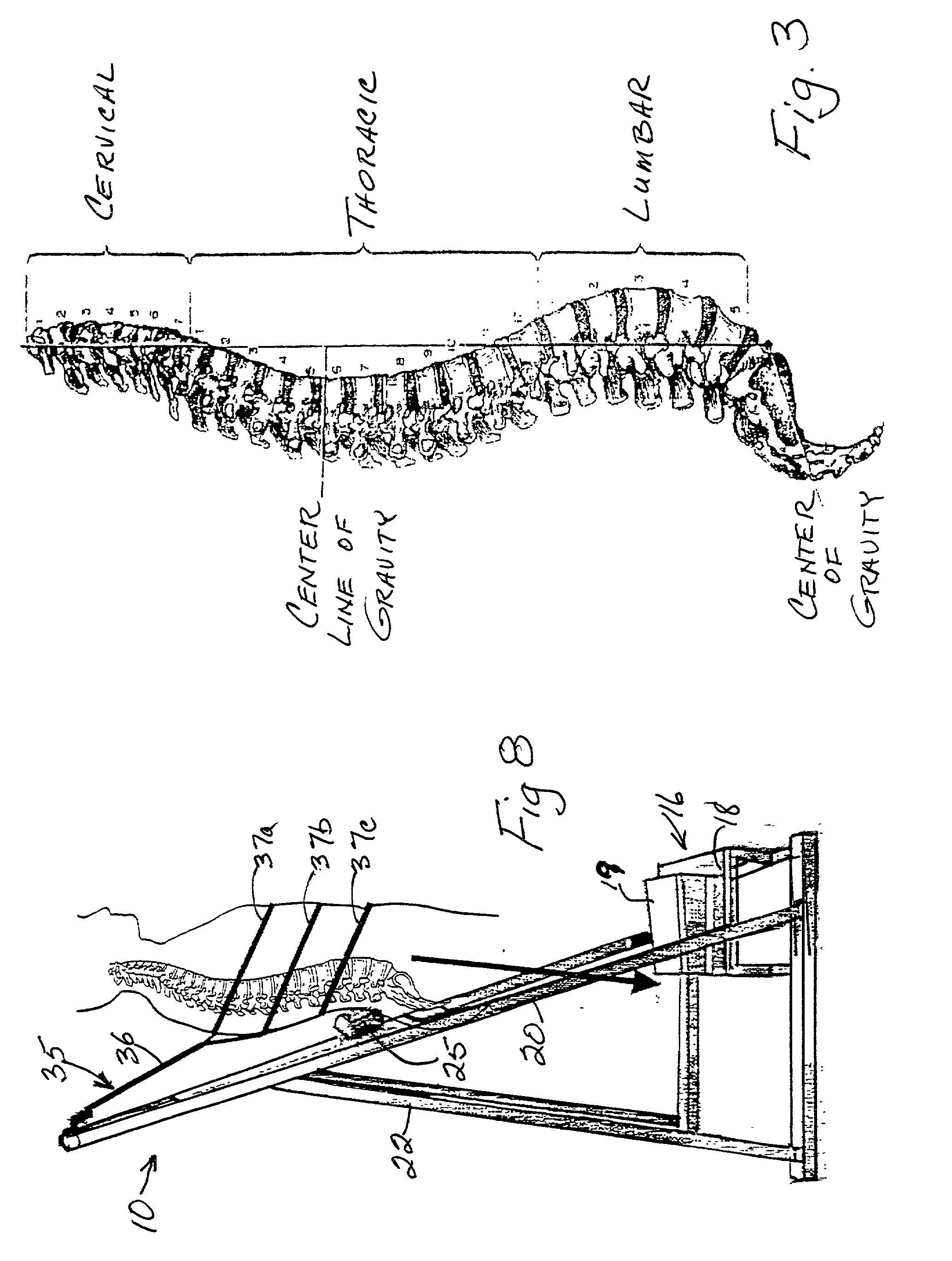
[0024] In a specific embodiment, the traction force means includes a spinal pressure element means for applying a portion of the patient's weight to a single focused traction area at a selected point along a patient's backbone that reduces pain-causing stress on the affected spinal area. The selected point may be generally referred to as an inflamed area. The patient's lower body freely suspends from the frame structure to allow for subtle side-to-side shifts in the patient's weight that produce a "balanced suspension" that increases the pull on tighter muscles. Depending on the amount of spasm present, the traction force draws up and shortens the tight muscles predominately on the affected side. So the hanging legs cause the side with the shortest muscles to take the bulk of the traction force thereby causing shorter muscles to be pulled harder and elongated. In short, the side undergoing the most spasm will receive the most force and benefit.
[0027] Clinical tests show that satisfactory results are often achieved using a particular protocol according to the invention. The protocol comprises a single treatment cycle composed of three (3) traction sessions of 20-30 seconds each separated by 30-90 second rest or non-traction periods. As patients are able to withstand longer stays in suspension with continued treatment, the time in traction may increase toward a 90 second duration. This treatment cycle of a series of short traction periods is repeated three alternate days a week for three weeks. Further treatment is effected on a case-by-case basis and depends on such factors as the patient's weight, physical condition, the extent of spinal damage prior to initiating traction treatment, emotional stability, and the degree of pain relief experienced using the traction assembly of the invention. A patient using the traction assembly of the invention often receives immediate relief, which is cumulative with repeated use. But a cautious and conservative treatment program is encouraged. Prolonged time in traction and / or excessive use of the device is discouraged.

Problems solved by technology

Back and leg pain frequently cause temporary and permanent disability of many people.
Many, however, do not get lasting relief and may even get worse.
A tilt board is unnecessary because patients vary the traction force merely by pushing their toes to the floor.

Method used


Image

  • Vertical traction assembly and method
  • Vertical traction assembly and method
  • Vertical traction assembly and method

Examples


Embodiment Construction

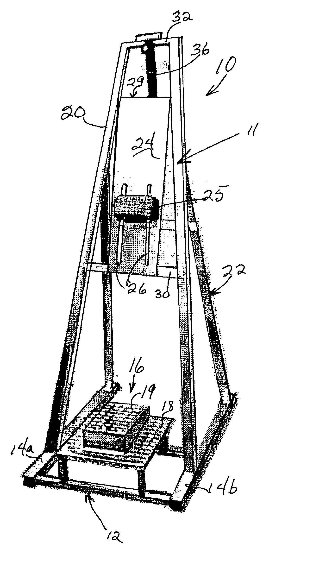
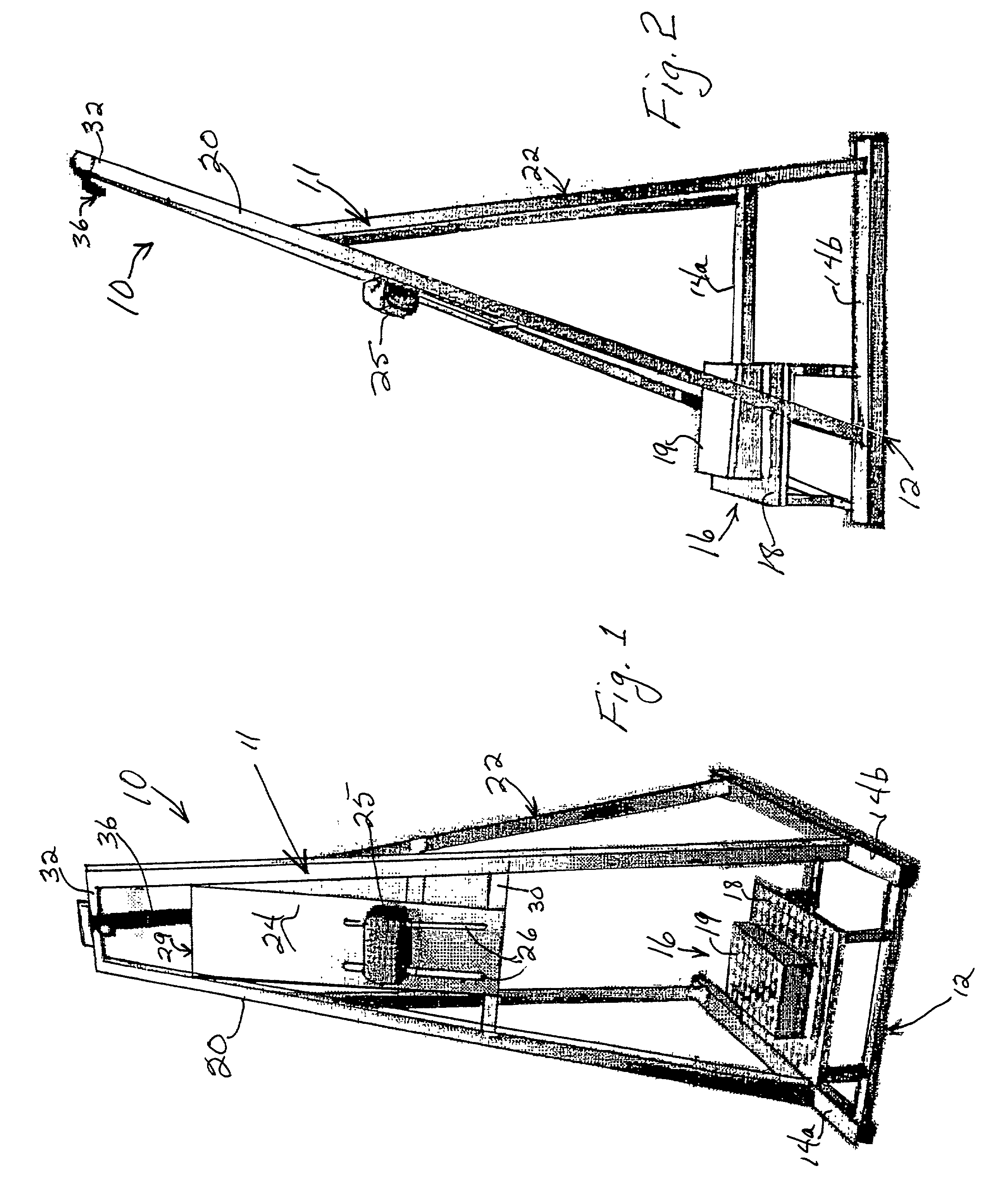
[0035] Traction assembly, generally designated 10 in FIGS. 1 and 2, includes a frame structure 11 having a front portion 20 and a rear portion 22 each fixedly secured to the other and to main base support elements 14a and 14b of base 12 as shown. Front frame portion 20 includes a backboard 24 fixedly mounted to upper board support member 29 and lower board support member 30. A torso harness 35 is attached to depend from upper frame cross-rail member 32. Traction focusing pad element 25 is adjustably mounted to two parallel slots 26 in backboard 24. Threaded stud bolt members project outwardly from the rear of pad element 25 and protrude through slots 26. And wing nut members releasably tighten pad element 25 to enable adjustment along backboard 24 to a desired position where element 25 is disposed adjacent an inflamed area of the patient's spine.

[0036] Frame structure 11 is free standing and composed of metal such as aluminum with the frame member connections welded together. The co...


PUM


Abstract

A vertical traction assembly for using gravity to stretch a person's spine comprises a frame structure and a torso harness combination coupled to depend from the frame structure. The harness combination is effective to maintain a person in a vertical traction position after the person dons the harness combination. A focused traction force mechanism is attached to the frame structure for applying a predetermined amount of focused traction pressure directly to a selected location along the spine of the person who is in the vertical traction position. A feature of the traction force mechanism may include its ability to be adjusted to different locations along the frame structure depending on the location of the afflicted area along the spine of the person being treated.

Description

[0001] This invention relates to a therapeutic traction assembly that enables persons being treated to control the time in which a gravity force may be applied to their spine. More particularly, the invention relates to a gravity traction assembly in which a person dons a torso harness depending from a frame structure and voluntarily steps into a suspended traction producing position.DESCRIPTION OF THE PRIOR ART[0002] Back and leg pain frequently cause temporary and permanent disability of many people. Inflammation regardless of cause (nerve compression, muscle strain, ligament tear, bone spur, arthritis, scar tissue, ruptured or degenerating disks) produces pain in addition to abnormal compression of bones that form the spinal column. Common therapy includes a period of bed rest, and the possible use of anti-inflammatory drugs such as aspirin and steroids. Such therapy is often sufficient to relieve the pain and end the attendant disability for the majority of people. Many, however...

Claims


Application Information

Patent Timeline
Patent Type & Authority Applications(United States)
IPC IPC(8): A61F5/04
CPCA61F5/04
Inventor PERREGO, DAVID W.
Owner PERREGO DAVID
Learn More