Screwing accessory device

a technology of screwing and accessory device, which is applied in the direction of screwdrivers, nailing tools, wrenches, etc., can solve the problems of reducing screwing efficiency, and achieve the effect of increasing screwing efficiency

Inactive Publication Date: 2017-11-28
WISTRON CORP
View PDF16 Cites 0 Cited by
  • Summary
  • Abstract
  • Description
  • Claims
  • Application Information

AI Technical Summary

Benefits of technology

[0006]The invention is directed to a screwing accessory device capable of increasing screwing efficiency.

Problems solved by technology

However, when a size of the screwed component is smaller than a finger, the screwed component is easy to drop, and thus a screwing efficiency is reduced.

Method used


Image

  • Screwing accessory device
  • Screwing accessory device
  • Screwing accessory device

Examples


Embodiment Construction

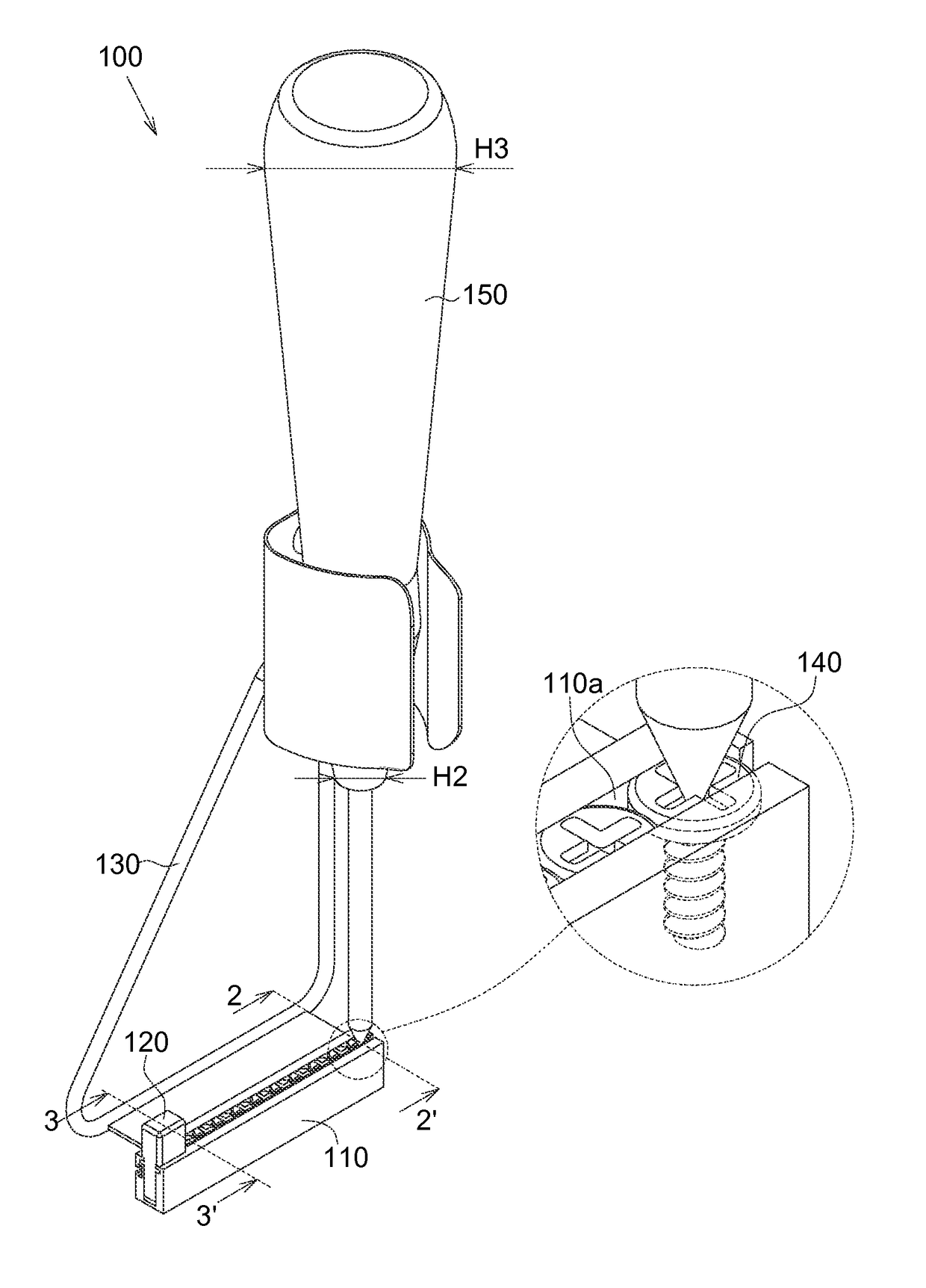
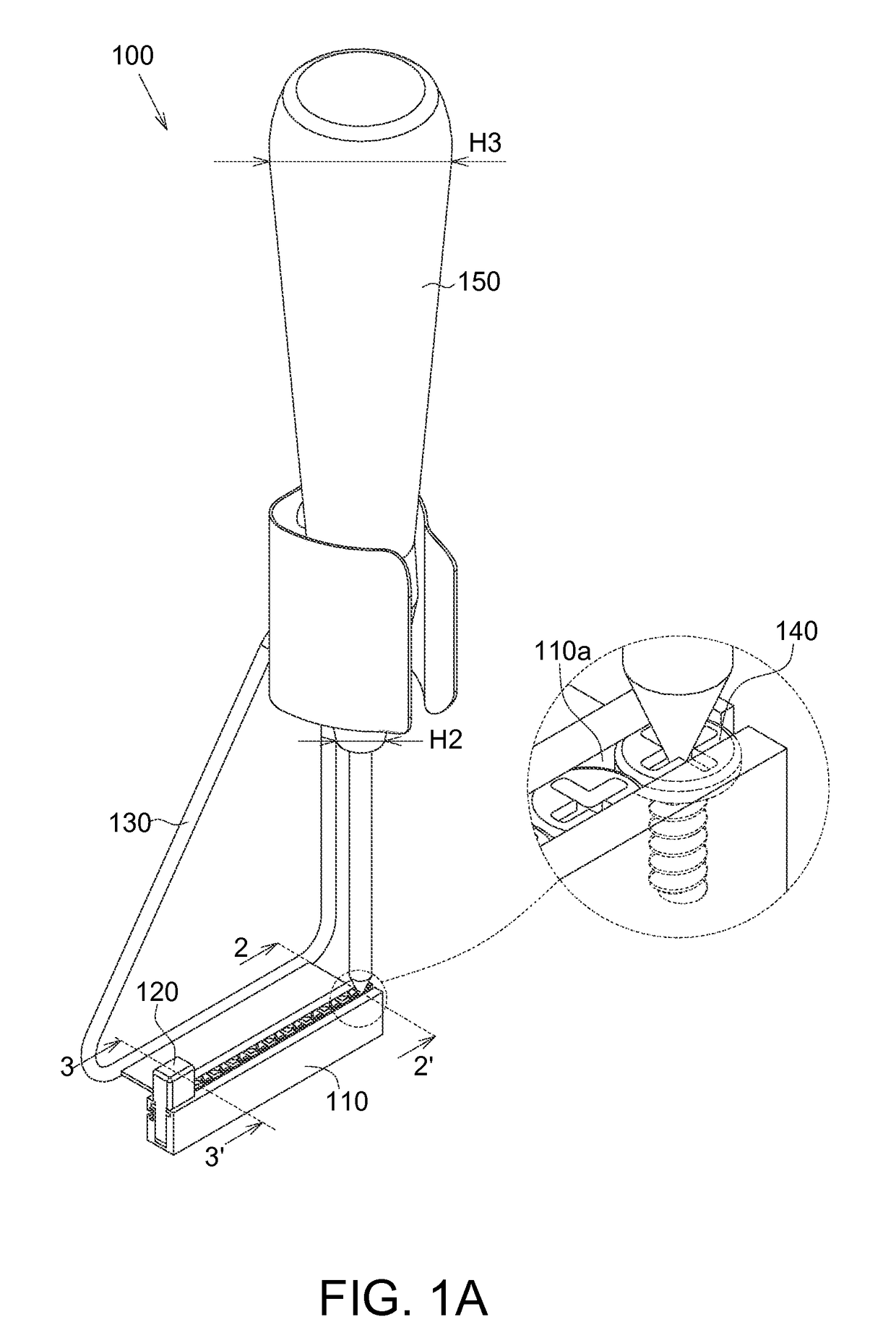
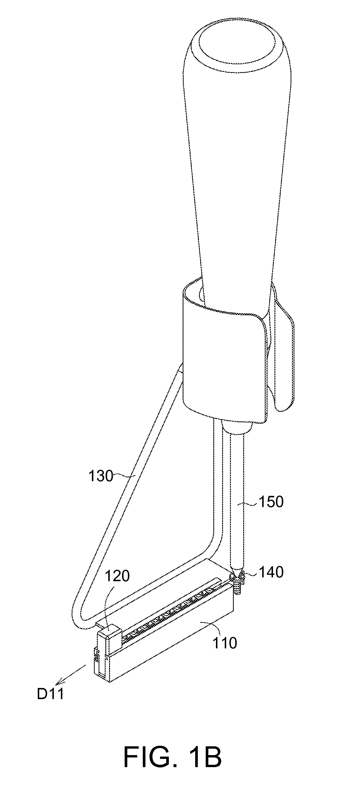
[0015]Referring to FIGS. 1A to 1E, an operation process of a screwing accessory device according to an embodiment of the invention is illustrated.

[0016]As illustrated in FIG. 1A, the screwing accessory device 100 comprises a receiving box 110, a pushing component 120 and the rack 130.

[0017]The receiving box 110 has a receiving space 110a to receive several screwed components 140. Accordingly, a problem of the screwed components 140 disorderly straggling down the ground or the top of the table and a problem of the screwed components 140 being easy to drop to the ground may be prevented. The screwing tool 150 is screwdriver, for example. The screwing tool 150 may be operated by hand to capture the screwed components 140. In detail, the rack 130 may be held by one hand, and the screwing tool 150 may be operated by another hand. In another embodiment, the screwing tool 150 may be operated by automatic equipment (such as robotic arm). In the present embodiment, an end 151 of the screwing...


PUM

PropertyMeasurementUnit
heightsaaaaaaaaaa
outer diameteraaaaaaaaaa
inner diameteraaaaaaaaaa

Abstract

The screwing accessory device comprises a receiving box, a rack and a pushing component. The receiving box is for receiving the screwed component. The rack is connected to the receiving box. The pushing component is disposed within the receiving box and is used for pushing the screwed component.

Description

[0001]This application claims the benefit of Taiwan application Serial No. 102223381, filed Dec. 11, 2013, the subject matter of which is incorporated herein by reference.BACKGROUND OF THE INVENTION[0002]Field of the Invention[0003]The invention relates in general to a screwing accessory device, and more particularly to a screwing accessory device having a receiving box for screwed components.[0004]Description of the Related Art[0005]It is usual to screw a screwed component to a workpiece. However, when a size of the screwed component is smaller than a finger, the screwed component is easy to drop, and thus a screwing efficiency is reduced. For this reason, how to make the screwing process more efficient is one goal for an industry in this technology field.SUMMARY OF THE INVENTION[0006]The invention is directed to a screwing accessory device capable of increasing screwing efficiency.[0007]According to one embodiment of the present invention, a screwing accessory device is provided. ...

Claims


Application Information

Patent Timeline
Patent Type & Authority Patents(United States)
IPC IPC(8): B25B15/02B25B23/06B25B23/12B25C1/00B25C5/16
CPCB25B15/02B25B23/06B25B23/12Y10T29/535B25C5/1606B25C5/1627B25C1/001
Inventor CHENG, JUI-KAIYU, CHIA-LIN
Owner WISTRON CORP
Why Eureka
Try Eureka