Electric vehicle control system

a control system and electric vehicle technology, applied in electric vehicle charging technology, electric devices, transportation and packaging, etc., can solve the problems of low control gain, control system destabilization, delay in communication, etc., to improve response and slip stop property, reduce communication delay effect, low control gain

Active Publication Date: 2017-11-28
HITACHI ASTEMO LTD
View PDF14 Cites 0 Cited by
  • Summary
  • Abstract
  • Description
  • Claims
  • Application Information

AI Technical Summary

Benefits of technology

[0003]A transmission path of the torque command transmits the command from the TCSECU 22 to the controller 23 and then outputs the command from the controller 23 to a motor. In other words, communication intervenes twice in the process of transmitting the torque command, which causes a delay in communication. If a control gain is increased to reduce an effect of the delay in communication, the control system is destabilized. The control gain then has to be set low. On the other hand, the low control gain makes it difficult to improve response and slip stopping property with respect to changes in a road surface condition (friction factor, for example). The invention has been made in light of the foregoing problem. It is an object of the invention to provide an electric vehicle control system capable of ensuring good response and slip stopping property with respect to changes in a road surface condition.

Problems solved by technology

In other words, communication intervenes twice in the process of transmitting the torque command, which causes a delay in communication.
If a control gain is increased to reduce an effect of the delay in communication, the control system is destabilized.
On the other hand, the low control gain makes it difficult to improve response and slip stopping property with respect to changes in a road surface condition (friction factor, for example).

Method used


Image

  • Electric vehicle control system
  • Electric vehicle control system
  • Electric vehicle control system

Examples


embodiment 1

Advantages of Embodiment 1

[0084]Operation and advantages provided by the electric vehicle control system according to the Embodiment 1 will be listed below.

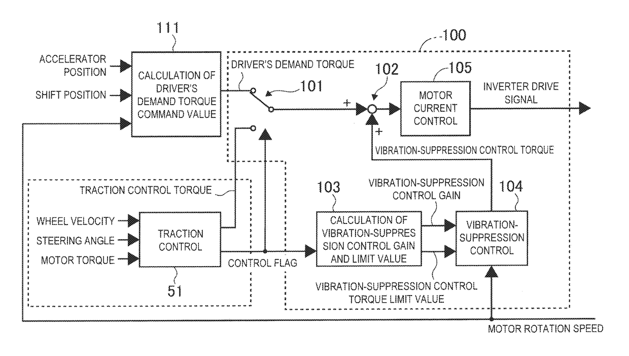
[0085](1) There is provided the electric vehicle control system comprising the wheel velocity sensor 9 (wheel velocity calculation unit) configured to calculate the velocities of the wheels; the electric motor 1 configured to generate a driving / braking force on the wheels; the hydraulic unit 5 (hydraulic braking device) configured to generate a hydraulic braking force on the wheels; the motor controller 100 configured to control the electric motor 1 according to the command value; the brake controller 50 (hydraulic controller) configured to calculate the braking force to be generated on the wheels by using the calculated wheel velocities and control the fluid pressure of the hydraulic unit 5 so as to generate the calculated braking force; the vehicle controller 110 configured to calculate the driver's demand torque command value ...

embodiment 2

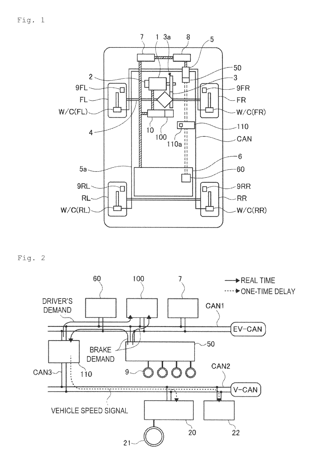
[0104]An Embodiment 2 will be now described. As the Embodiment 2 has a basic structure identical to that of the Embodiment 1, the following descriptions refer only to differences between these two embodiments. FIG. 19 is a schematic view showing connection of various controllers according to the Embodiment 2. In an electric vehicle of the Embodiment 2, the battery controller 60, the motor controller 100, and the inverter 10, configured to control the torque condition which effects between the drive wheels and a road surface, are connected to the first CAN bus CAN1 as a power train system. A chassis system including the power steering controller 20 and the meter controller 22 is connected to the second CAN bus CAN2.

[0105]The first CAN bus CAN1 and the second CAN bus CAN2 are connected to each other by the first connection bus CAN3 and a second connection bus CAN4. The first connection bus CAN3 is provided with the vehicle controller 110. Information transmitted and received through t...

embodiment 3

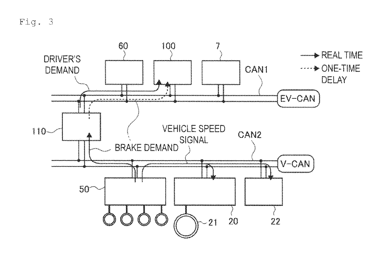
[0108]An Embodiment 3 will be now described. As the Embodiment 3 has a basic structure identical to that of the Embodiment 1, the following descriptions refer only to differences between these two embodiments. FIG. 20 is a schematic view showing connection of various controllers according to the Embodiment 3. In the electric vehicle of the Embodiment 3, the battery controller 60 and the inverter 10 configured to control the torque condition which effects between the drive wheels and a road surface are connected to the first CAN bus CAN1 as a power train system. A chassis system including the brake controller 50, the power steering controller 20 and the meter controller 22 is connected to the second CAN bus CAN2.

[0109]The first CAN bus CAN1 and the second CAN bus CAN2 are connected to each other by the first connection bus CAN3 and the second connection bus CAN4. The first connection bus CAN3 is provided with the vehicle controller 110. Information transmitted and received through th...


PUM


Abstract

Provided is an electric vehicle control system capable of securing good response and slip stopping property with respect to changes in a road surface condition. The system includes a vehicle controller configured to calculate a driver's demand torque command value according to a driver's accelerating or braking operation, a first communication device capable of communicating between a hydraulic controller and a motor controller, and a second communication device capable of communicating between the vehicle controller and the motor controller. The system includes a control system in which the hydraulic controller transmits a motor torque command value to the motor controller through the first communication device; the vehicle controller transmits the driver's demand torque command value to the motor controller through the second communication device; and the motor controller selects either one of the received motor torque command value and the received driver's demand torque command value as the command value.

Description

TECHNICAL FIELD[0001]The invention relates to a control system for an electric vehicle.BACKGROUND ART[0002]A conventionally-known control system for an electric vehicle is described in Japanese Unexamined Patent Application Publication No. 2007-74817. According to the electric vehicle mentioned in the document, when a TCS demand torque is outputted from a TCSECU 22, a switching command is outputted to a power drive unit 15 through a drive-train torque calculation unit 43 and a motor torque control unit 42 of a controller 23 to control motor torque.SUMMARY[0003]A transmission path of the torque command transmits the command from the TCSECU 22 to the controller 23 and then outputs the command from the controller 23 to a motor. In other words, communication intervenes twice in the process of transmitting the torque command, which causes a delay in communication. If a control gain is increased to reduce an effect of the delay in communication, the control system is destabilized. The con...

Claims


Application Information

Patent Timeline
Patent Type & Authority Patents(United States)
IPC IPC(8): B60W10/08B60L3/00B60R16/023B60L15/20B60L3/10B60L3/12B60L7/18B60L7/26B60W30/18B60W10/184B60W50/00
CPCB60L15/2009B60L3/0084B60L3/102B60L3/106B60L3/12B60L7/18B60L7/26B60L15/20B60R16/023B60W10/08B60W10/184B60W30/18172B60L3/0076Y02T90/16B60L2240/423B60L2240/461B60L2250/26B60L2260/44B60W2050/0006B60W2050/0045B60W2050/0094B60W2550/148Y02T10/645Y02T10/7275B60W2552/40Y02T10/64Y02T10/72
Inventor SUZUKI, KEISUKEKOBAYASHI, HITOSHIYAMAMOTO, TATSUYUKI
Owner HITACHI ASTEMO LTD
Why Eureka
Try Eureka