
Harness routing structure for electric vehicle

a technology for electric vehicles and routing structures, applied in electric propulsion mounting, battery/cell propulsion, transportation and packaging, etc., to achieve the effect of reducing the amount of allowance (deflection) and reducing the cost of normal charging harnesses

Active Publication Date: 2017-11-28
NISSAN MOTOR CO LTD
View PDF6 Cites 3 Cited by
  • Summary
  • Abstract
  • Description
  • Claims
  • Application Information

AI Technical Summary

Benefits of technology

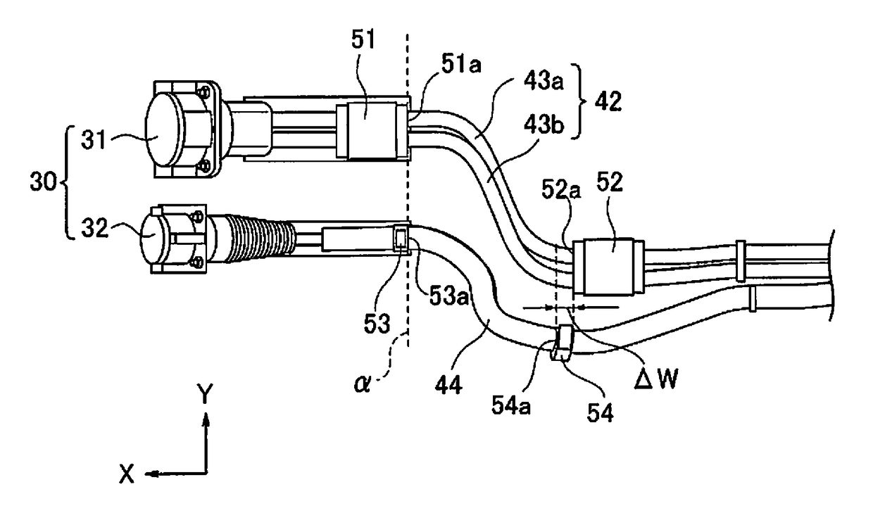
The present invention provides a harness routing structure for an electric vehicle that prevents interference between charging harnesses when connecting the power unit and charging port using a quick charging harness and a normal charging harness. This is achieved by configuring the normal charging harness to be shorter in length, so that it is less flexible and less likely to be deformed in response to vibration. As a result, the normal charging harness is less likely to come into contact with the quick charging harness and prevent interference.

Problems solved by technology

This causes a problem to produce different vibration states or modes between the normal charging harness and the quick charging harness so that the normal charging harness may contact with the quick charging harness.

Method used


Image

  • Harness routing structure for electric vehicle
  • Harness routing structure for electric vehicle
  • Harness routing structure for electric vehicle

Examples


first embodiment

[0023]First, the configurations in the harness routing structure for an electric vehicle in the first embodiment will be described in the “basic configuration of the electric vehicle”, the “routing structure of the quick charging harness”, and the “routing structure of the normal charging harness”, separately.

Basic Configuration of the Electric Vehicle

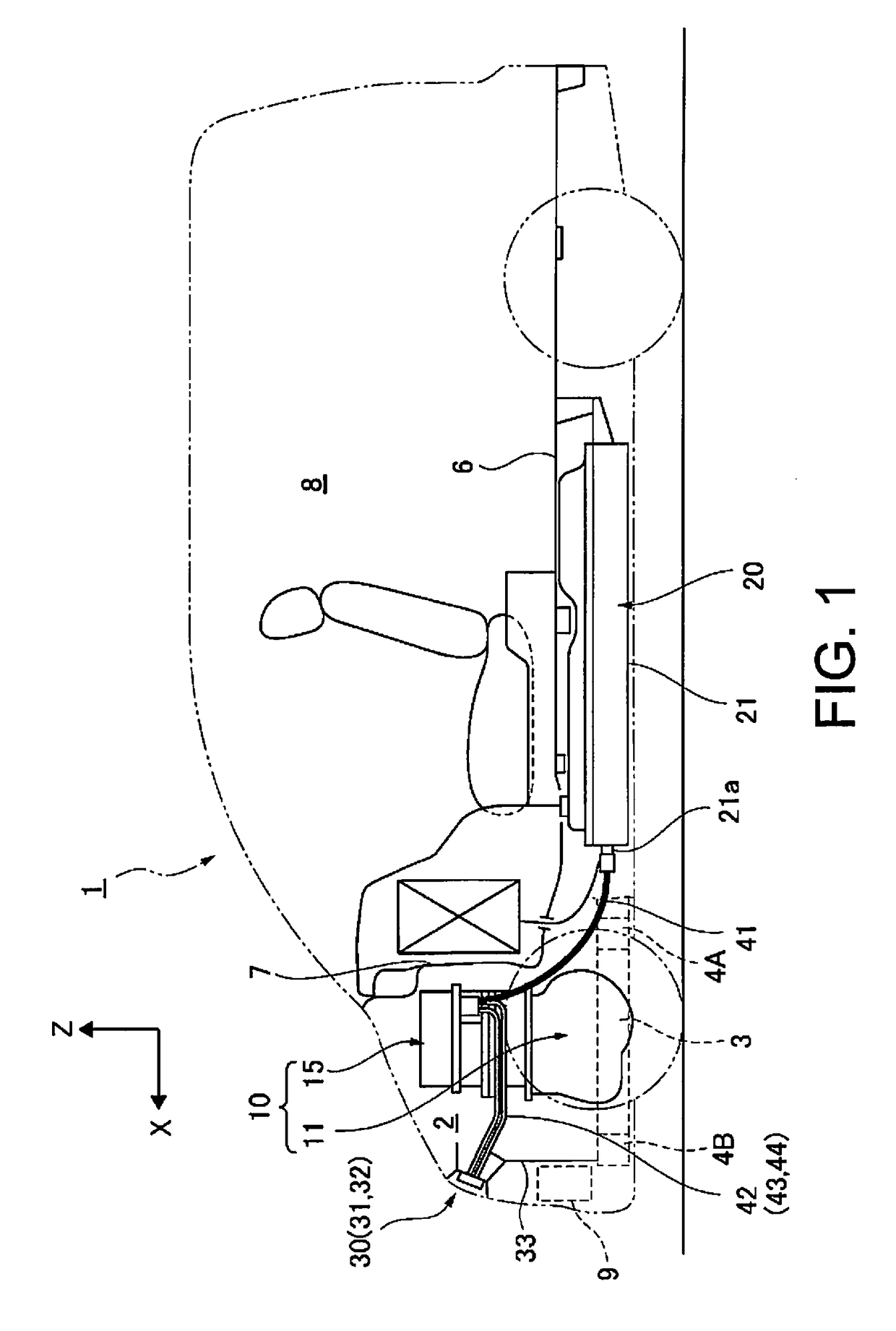
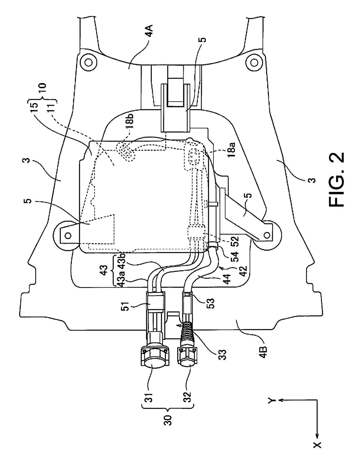
[0024]FIG. 1 is an overall side view showing a main structure of an electric vehicle to which the harness routing structure in a first embodiment is applied. FIG. 2 is a schematic plan view showing a front main structure of an electric vehicle to which the harness routing structure of the first embodiment is applied. FIG. 3 is a schematic side view showing the front main structure of an electric vehicle to which the harness routing structure of the first embodiment is applied. In the drawings, the direction indicated by the arrow X is the vehicle longitudinal direction, the direction indicated by the arrow Y is the vehicle width direct...


PUM


Abstract

An electric vehicle harness routing structure is provided for an electric vehicle having an electric motor as a drive source, a control device to control the electric motor as well as charging of a battery for power supply to the electric motor, and a power unit elastically supported on a vehicle body. The harness routing structure includes a charging port, a quick charging harness, a normal charging harness, a first quick-charge harness clip, a second quick-charge harness clip, a first normal-charge harness clip and a second normal-charge harness clip. The clips of the electric vehicle harness routing structure is provided such that when connecting a relatively movable power unit and charging ports with the quick charging harness and the normal charging harness, it is possible to prevent interference of between the charging harnesses.

Description

[0001]This application is a U.S. National stage application of International Application No. PCT / JP2013 / 055637, filed Mar. 1, 2013, which claims priority to Japanese Patent Application No. 2012-047801 filed in Japan on Mar. 5, 2012. The entire disclosure of Japanese Patent Application No. 2012-047801 is hereby incorporated herein by reference.BACKGROUND[0002]Field of the Invention[0003]The present invention relates to a harness routing structure for an electric vehicle in which a power unit and a charging port are connected by a charge cable or harness.[0004]Background Information[0005]Conventionally, it is known that a converter, a charger, and a charging port are fixed respectively to a vehicle body for charging control of a power supply battery for a vehicle propulsion electric motor. The charging port and the converter are connected by a pair of quick charge cables or harnesses while the charging port and the charger are connected by a normal charge harness (for example, see Jap...

Claims


Application Information

Patent Timeline
Patent Type & Authority Patents(United States)
IPC IPC(8): B60R16/02B60K1/04B60L11/18B60L7/14
CPCB60R16/0215B60L7/14B60L11/1803B60L11/185B60L11/1809B60L11/1818B60L11/1877B60K1/04Y02T90/14B60L2210/10B60L2210/30B60L2210/40B60L2270/145B60L2270/147Y02T10/7005Y02T10/705Y02T10/7072Y02T10/7216Y02T10/7241Y02T90/121Y02T90/127Y02T90/128B60L50/51B60L50/66B60L53/11B60L53/16Y02T10/70Y02T10/72Y02T90/12
Inventor MATANO, SHINICHIIINO, KENJIONISHI, MASAHIRO
Owner NISSAN MOTOR CO LTD
Learn More