Supercharge Your Innovation With Domain-Expert AI Agents!

Pressure regulator and hydraulic brake system for vehicle equipped with the same

a technology of hydraulic brake system and pressure regulator, which is applied in the direction of braking system, functional valve type, valve housing, etc., can solve the problems of unlikely foreign matter to be caught, the spool valve mechanism is unlikely to suffer from the troubles experienced, and the poppet valve mechanism may suffer from troubles. , to achieve the effect of high reliability

Active Publication Date: 2017-11-28
TOYOTA JIDOSHA KK
View PDF17 Cites 1 Cited by
  • Summary
  • Abstract
  • Description
  • Claims
  • Application Information

AI Technical Summary

Benefits of technology

[0010]The pressure regulator constructed according to the invention includes a spool valve mechanism and is thus excellent in various aspects. For instance, foreign matters are unlikely to be caught. The present pressure regulator includes a counter biasing mechanism configured to bias the spool against the pilot pressure. The counter biasing mechanism is configured not to directly apply the pressure of the working fluid supplied from the pressure regulator (hereinafter referred to as “regulated pressure” where appropriate) to an end face of the spool, but is configured to bias the spool via the counter biasing piston. In a case where it is desired to increase a biasing force by the pilot pressure, for instance, a pressure receiving area of the piston with respect to the regulated pressure is increased, whereby it is possible to easily increase a biasing force against the pilot pressure. In other words, the invention achieves the pressure regulator having good response with the diameter of the spool kept small. Thus, the pressure regulator according to the invention has high utility.
[0052]In short, the hydraulic brake system according to this form employs the pressure regulator in various forms described above. According to the system of this form, in the normal condition, the pressure regulator conducts pressure regulation utilizing, as the first pilot pressure, the pressure of the working fluid adjusted by the pressure adjusting device. In an instance where the pressure adjusting device fails to operate due to electric failure or the like, the pressure regulator may conduct pressure regulation utilizing, as the second pilot pressure, a pressure of the working fluid having a level in accordance with the brake operation force (hereinafter referred to as “operation-force dependent pressure” where appropriate) or a pressure of the working fluid to be supplied form the master cylinder device to the brake device (hereinafter referred to as “master pressure” where appropriate). The thus constructed hydraulic brake system has a high reliability.

Problems solved by technology

In the poppet valve mechanism, a clearance between the valve member and the valve seat formed when the valve member is separated away from the valve seat is relatively large, and the poppet valve mechanism thus may suffer from troubles.
Such a spool valve mechanism is unlikely to suffer from the troubles experienced in the poppet valve mechanism.
For instance, foreign matters are unlikely to be caught.

Method used


Image

  • Pressure regulator and hydraulic brake system for vehicle equipped with the same
  • Pressure regulator and hydraulic brake system for vehicle equipped with the same
  • Pressure regulator and hydraulic brake system for vehicle equipped with the same

Examples


embodiment 1

1. Overall Structure

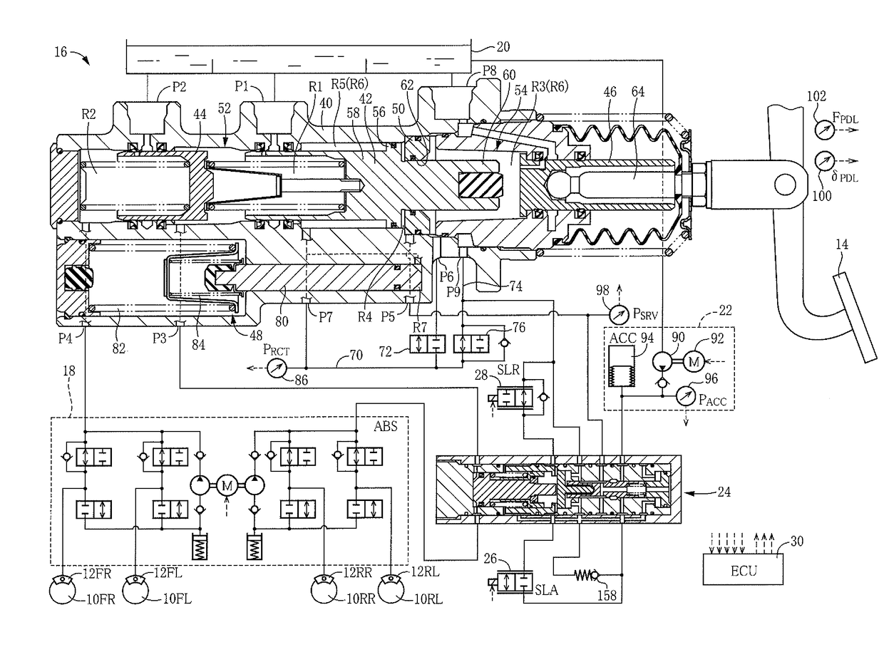
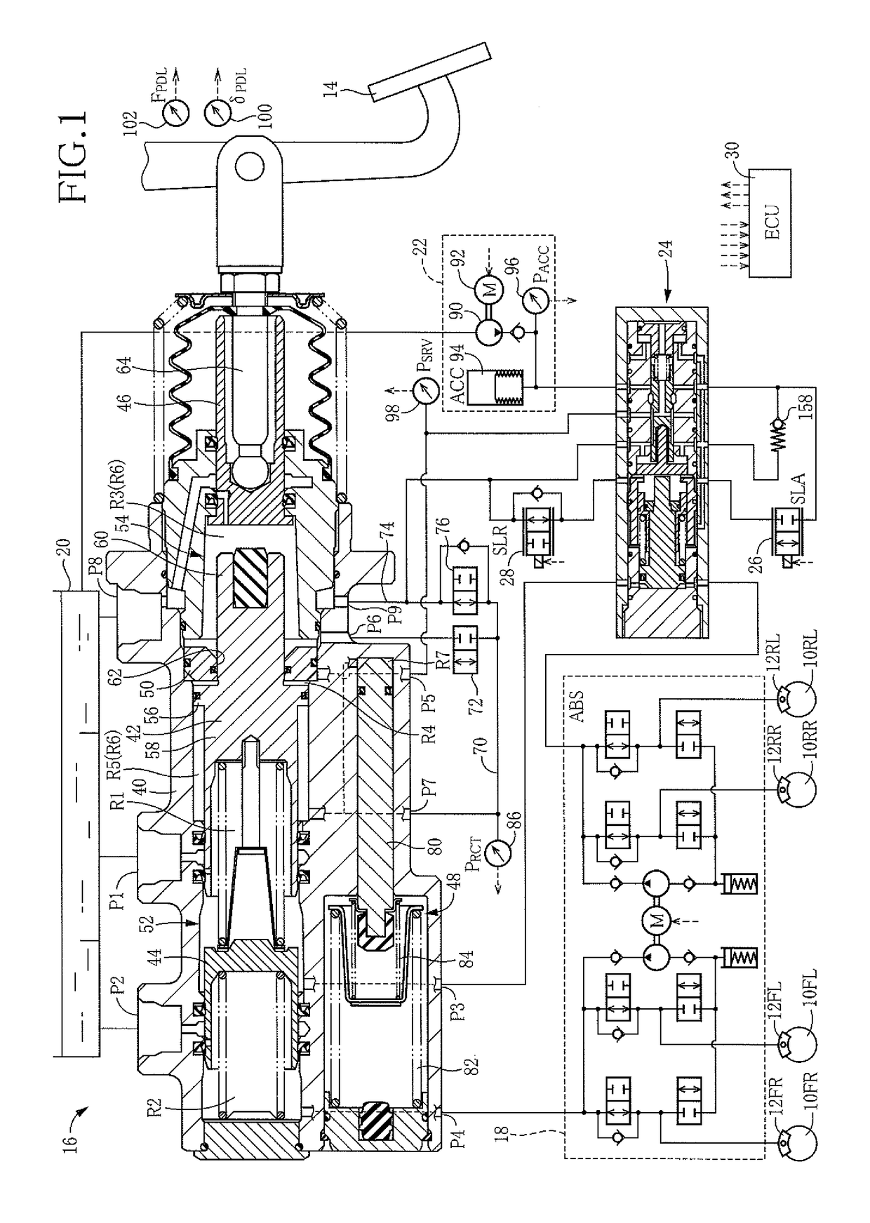
[0058]A hydraulic brake system for a vehicle according to a first embodiment is installed on hybrid vehicles in which a brake oil is used as a working fluid. As shown in FIG. 1, the present hydraulic brake system generally includes (A) four brake devices 12 which are provided for respective four wheels 10 and each of which is configured to generate a braking force, (B) a master cylinder device 16 to which is input an operation of a brake pedal 14 as a brake operation member and which is configured to supply a pressurized working fluid to each brake device 12, (C) an antilock unit 18, as an ABS device, disposed between the master cylinder device 16 and the four brake devices 12, (D) a high-pressure-source device 22, as a high-pressure source, configured to pump up the working fluid from a reservoir 20 as a low-pressure source and to pressurize the pumped fluid, so as to supply the working fluid that is highly pressurized, (E) a regulator 24, as a mechanical pressu...

embodiment 2

[0103]A hydraulic brake system for a vehicle according to a second embodiment differs from the system in the illustrated first embodiment in that the regulator 24 of the first embodiment is changed to another pressure regulator. In view of this, explanation of the hydraulic brake system of the second embodiment is limited to explanation of the pressure regulator.

[0104]The pressure regulator employed in the hydraulic brake system of the second embodiment is a regulator 200 shown in FIG. 3. The regulator 200 is similar in construction to the regulator 24 in the first embodiment. In view of this, the same reference numerals as used in the regulator 24 are used to identify members and portions of the regulator 200 that have the same functions, and explanation of which is omitted to some extent. The regulator 200 will be explained focusing on structures of the regulator 200 different from the regulator 24.

[0105]Like the regulator 24, the regulator 200 includes, as a main constituent elem...

modified examples

[0116]The hydraulic brake system according to each of the illustrated two embodiments is configured such that the working fluid to be supplied from the master cylinder device 16 to the brake devices 12, namely, the working fluid having the master pressure PMST, is introduced into the regulator 24, 200 as the working fluid having the second pilot pressure PPLT2. In place of the working fluid having the master pressure PMST, the working fluid having a pressure corresponding to a level in accordance with the brake operation force may be introduced into the second-pilot-pressure chamber. Such a working fluid enables appropriate pressure regulation by the regulator 24, 200 in the event of electric failure or the like, so that the hydraulic brake system can generate an appropriate braking force in the brake devices 12. Specifically, the working fluid in the inter-piston chamber R3 may be introduced into the second-pilot-pressure chamber. In the master cylinder device 16, the inter-chamber...


PUM


Abstract

A pressure regulator configured to regulate a pressure of a working fluid by two pilot pressures, including: a spool valve mechanism having a spool; a first biasing mechanism configured to bias the spool toward the other end of the pressure regulator in its axial direction by a first pilot pressure in a first-pilot-pressure chamber; a second biasing mechanism configured to bias the spool toward the other end of the pressure regulator by a second pilot pressure in a second-pilot-pressure chamber; and a counter biasing mechanism configured to bias the spool toward one end of the pressure regulator by a pressure of the working fluid in a regulated-pressure chamber, wherein the counter biasing mechanism has a counter biasing piston configured to push the spool toward the one end of the pressure regulator by the pressure of the working fluid in the regulated-pressure chamber applied to the counter biasing piston.

Description

CROSS REFERENCE TO RELATED APPLICATION[0001]The present application claims priority from Japanese Patent Application Nos. 2014-168246 and 2014-168249 which were filed on Aug. 21, 2014 and No. 2014-206990 which was filed on Oct. 8, 2014, the disclosure of which is herein incorporated by reference in its entirety.BACKGROUND OF THE INVENTION[0002]Field of the Invention[0003]The present invention relates to a pressure regulator configured to regulate a pressure of a working fluid supplied from a high-pressure source and also relates to a hydraulic brake system for a vehicle including the pressure regulator.[0004]Description of the Related Art[0005]In the field of a vehicle hydraulic brake system, a system is known in which a brake device generates a braking force depending not on a brake operation force but mainly on a pressure of a working fluid supplied from a high-pressure source. In the system, a pressure regulator is used for regulating the pressure of the working fluid supplied fr...

Claims


Application Information

Patent Timeline
Patent Type & Authority Patents(United States)
IPC IPC(8): B60T13/14B60T13/68B60T13/66F16K11/06B60T13/16F16K17/04B60T7/04
CPCF16K17/0473B60T7/042B60T13/146F16K11/06B60T13/662B60T13/686B60T13/167B60T13/142F16K11/07F16K27/041
Inventor ISONO, HIROSHI
Owner TOYOTA JIDOSHA KK
Features
  • R&D
  • Intellectual Property
  • Life Sciences
  • Materials
  • Tech Scout
  • Unparalleled Data Quality
  • Higher Quality Content
  • 60% Fewer Hallucinations
Learn More