Control device for power supply time of timers

a control device and timer technology, applied in the field of timer control devices, can solve the problems of inefficient power supply on demand, user choice not quite many, and inability to meet the needs of users,

Inactive Publication Date: 2017-11-28
YU CHAO CHENG
View PDF4 Cites 3 Cited by
  • Summary
  • Abstract
  • Description
  • Claims
  • Application Information

AI Technical Summary

Benefits of technology

[0006]A control device for power supply time of timers is disclosed, which is electrically connected to a power grid end and at least a load end, wherein the control device for power supply time of timers comprises: an alternative current (AC) power source input module, used to input AC power; a direct current (DC) power source supply module, which is electrically connected to the AC power source input module and used to convert the AC power into the DC power; an AC power source output module, which is electrically connected to a load end in order to output the AC power to the load end; a relay, which is electrically connected to the AC power source input module, the DC power source supply module and the AC power source output module, wherein the relay is used to control whether the AC power inputted by the AC power source input module should pass through the relay to supply the power to the AC power source output module such that the AC power source output module can output the AC power to the load end; a central control module, which is electrically connected to the DC power source supply module in order to control the integral operation mechanism of the control device for power supply time of timers; a day/night detecting module, which is electrically connected to the central control module for detecting the sunrise and sunset conditions and transferring the signal indicating the sunrise and sunset conditions of each day to the central control module thereby allowing the central control module to determine and record the sunrise time and sunset time of each day; a relay driver circuit, which is electrically connected to the central control module and the relay, in which the central control module is able to connect to the relay by means of the relay driver circuit such that electric power can be supplied to the AC power source output module; a power supply time backward display light set, which includes at least one power supply time backward display light and is electrically connected to the central control module, wherein each of the power supply time back...

Problems solved by technology

However, this type of mechanical countdown timers may be simple and direct, the number of wheel disc rotations just represents the extent of the intended power supply time, so it can not be configured to operate for longer power supply time; besides, since the available power supply time that the mechanical countdown timer can be rotated to may be limited, users actually don't have quite many choices for the desired length of power supply time.
Moreover, because the mechanical countdown timers are unable to display the currently remaining power supply time, the user can not precisely appreciate the currently remaining power supply tim...

Method used


Image

  • Control device for power supply time of timers
  • Control device for power supply time of timers
  • Control device for power supply time of timers

Examples


first embodiment

[0046]Next, the present invention shown in FIG. 6A is provided, illustrated as below:

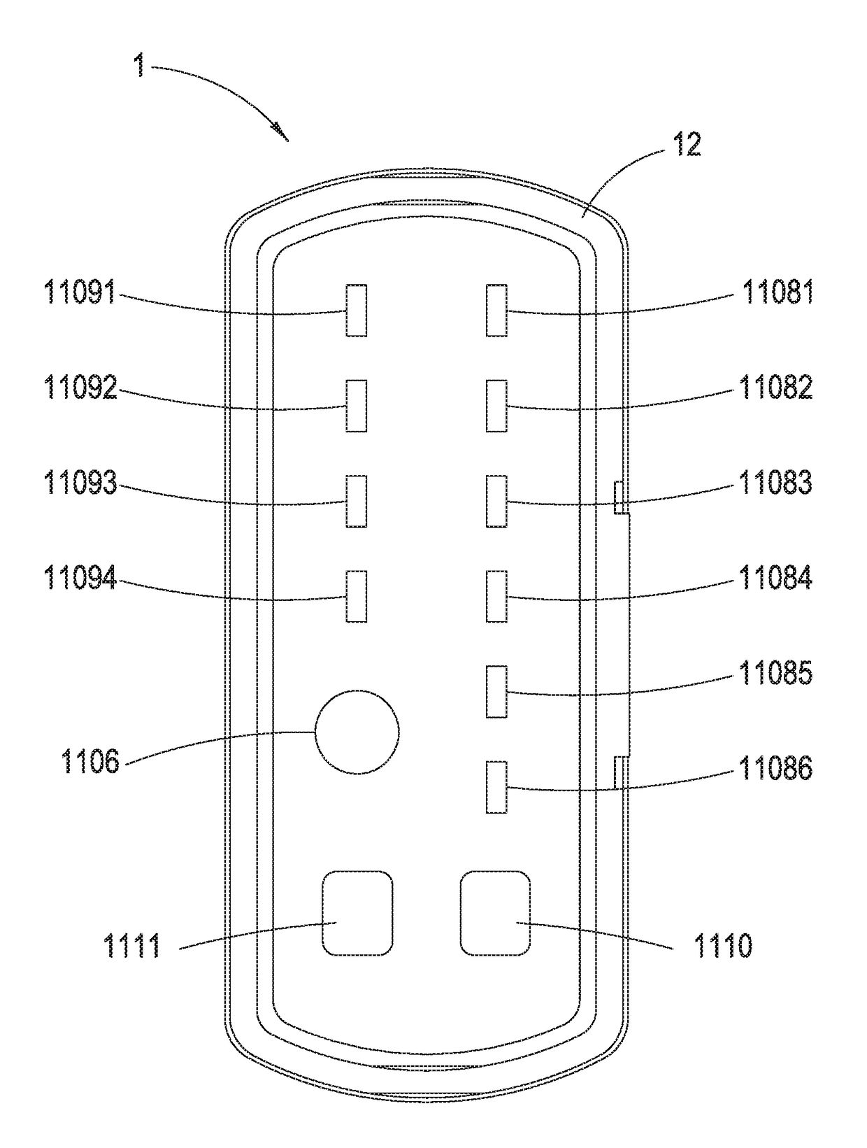
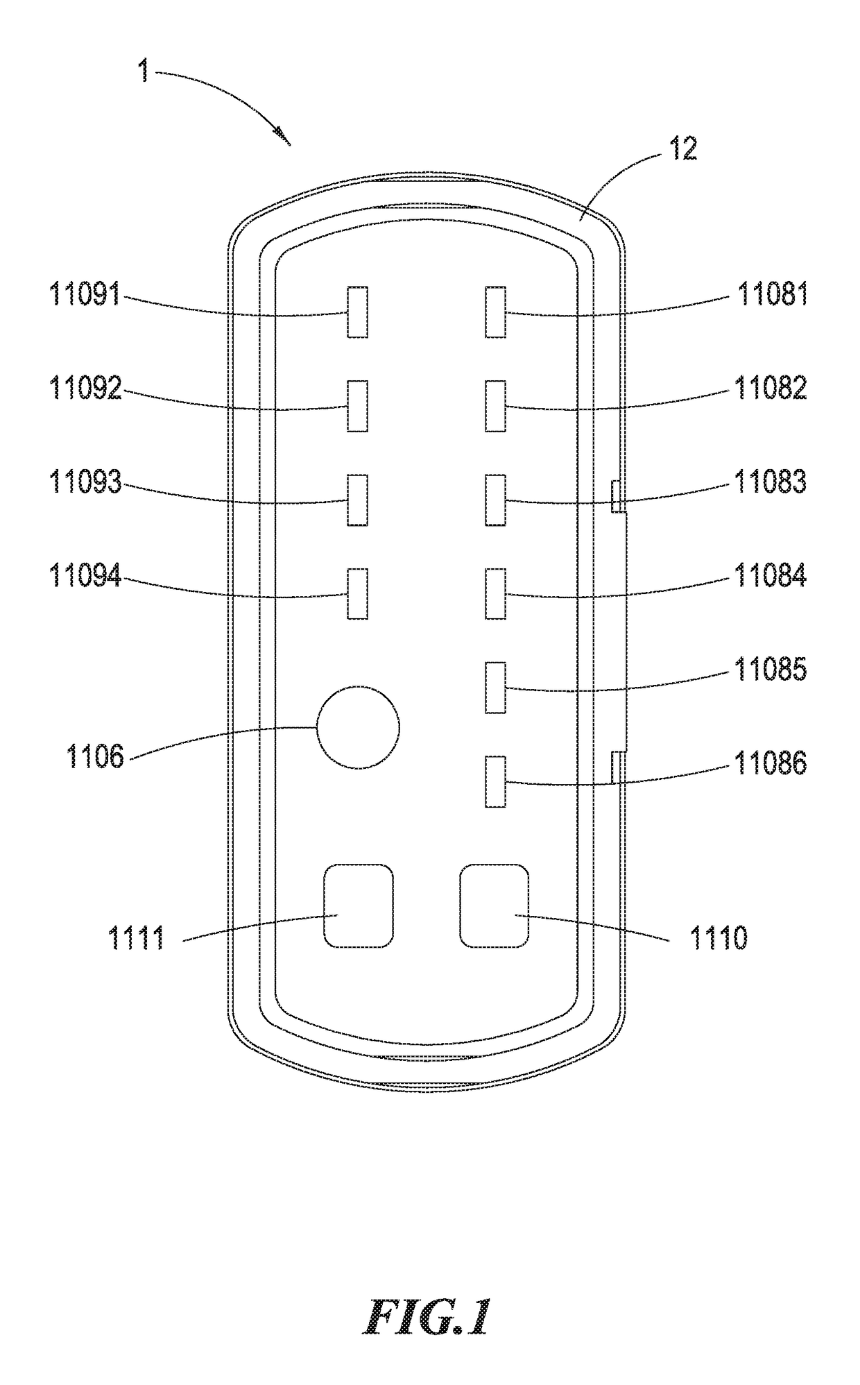
[0047](1) when the power supply time backward display light set 1108 is configured to be 1 H / 2 H / 4 H / 8 H and the function of the power supply time forward display light set 1109 is enabled, then, in the first day, the approach that the day / night detecting module 1106 determines the sunset is activating the output to be ON upon detecting the sunset for continuous 10 seconds;

[0048](2) at this time, it needs to continuously detect the sunset time; suppose the detection of sunset is indeed confirmed, then the entry moment of this sunset time is recorded, wherein this operation of sunset time recording is performed once a day and this sunset time can be applied in the next day.

second embodiment

[0049]Subsequently, the present invention shown in FIG. 6B is provided, illustrated as below:

[0050](1) when the power supply time backward display light set 1108 is configured to be 1 H / 2 H / 4 H / 8 H and the function of the power supply time forward display light set 1109 is enabled, then, after the second day, only when the determined sunset time is really confirmed as the sunset can the entry time to this sunset be recorded;

[0051](2) the output action is based on the sunset time recorded in the previous day to accordingly configure the time of the power supply time forward display light set 1109 to the recorded sunset time of the previous day thereby advancing the time setting of the power supply time forward display light set 1109 for operations.

[0052]Furthermore, an illustration for the continuation from the second embodiment of the present invention shown in FIG. 6C is provided, whose method can be illustrated as below:

[0053](1) assume the power supply time backward display light...


PUM


Abstract

A control device for power supply time of timers comprises an alternative current (AC) power source input module, a direct current (DC) power source supply module, an AC power source output module electrically connected to a load end, a relay, a central control module, a relay driver circuit, a day/night detecting module, a power supply time backward display light set, a power supply time forward display light set, a power supply time backward selection control button and a power supply time forward selection control button. Herein, by pressing the power supply time backward selection control button or the power supply time forward selection control button, one of the power supply time backward display lights or the power supply time forward display lights can be turned on such that the central control module can, based on the sunset time of the previous day as well as the configured power supply backward setting time or power supply forward setting time, postpone or advance the power supply time for the load end in the next day, and then record the sunset time of the next day so as to control the power supply time for the load end in the further next day.

Description

BACKGROUND OF THE INVENTION1. Field of the Invention[0001]The present invention generally relates to a control device for power supply time of timers; in particular, it relates to a control device for power supply time capable of forwardly configuring the power supply time of the next day based on the sunset time of the previous day.2. Description of Related Art[0002]It is well-known that most of the electric power socket devices enabling the timing feature may be equipped with a timer which can be a type of mechanical countdown timer; taking this sort of timer including a wheel disc as an example, a user may need to rotate the wheel disc installed on the timer so as to set up the countdown duration of time to control the power supply time of the electric power socket device thereby saving the power consumption of the electric devices plugged into the electric power socket device.[0003]However, this type of mechanical countdown timers may be simple and direct, the number of wheel di...

Claims


Application Information

Patent Timeline
IPC IPC(8): H02M7/02H02J3/00G04B19/22H01H47/00
CPCH02J3/00H01H47/00H01H47/001H01H47/223H01H47/32H02J2310/12H02J3/14Y04S20/222Y02B70/3225
Inventor YU, CHAO-CHENG
Owner YU CHAO CHENG
Why Eureka
Try Eureka