
Fastening device and fastening method

a technology of fastening device and control panel, which is applied in the direction of electrical apparatus casing/cabinet/drawer, insulated conductor, cable, etc., can solve the problems of affecting installation and user experience, and the difficulty of controlling the torque within the required range, so as to achieve easy and quick installation

Active Publication Date: 2017-11-28
SIEMENS AG
View PDF27 Cites 0 Cited by
  • Summary
  • Abstract
  • Description
  • Claims
  • Application Information

AI Technical Summary

Benefits of technology

Enables quick, stable, and reliable fastening of control panels to distribution boxes without the need for manual torque control, allowing for easy installation and disassembly by hand, with a constant fastening force and compatibility with various iron plate thicknesses.

Problems solved by technology

However, if the user adopts a manual installation method, it is difficult to control the torque within the required range, which would easily lead to the tilting of the installation snap together with the screw, thereby affecting the installation and user experience.
To this end, how to make it possible for a distribution box control panel, such as an HMI and NC panel, to be quickly and easily installed and fixed on the distribution box becomes a problem to be solved urgently in the art.

Method used


Image

  • Fastening device and fastening method
  • Fastening device and fastening method
  • Fastening device and fastening method

Examples


Embodiment Construction

[0032]In order to make the object, technical solution and advantages of the present invention become more apparent, the present invention is described in further detail via the following embodiments.

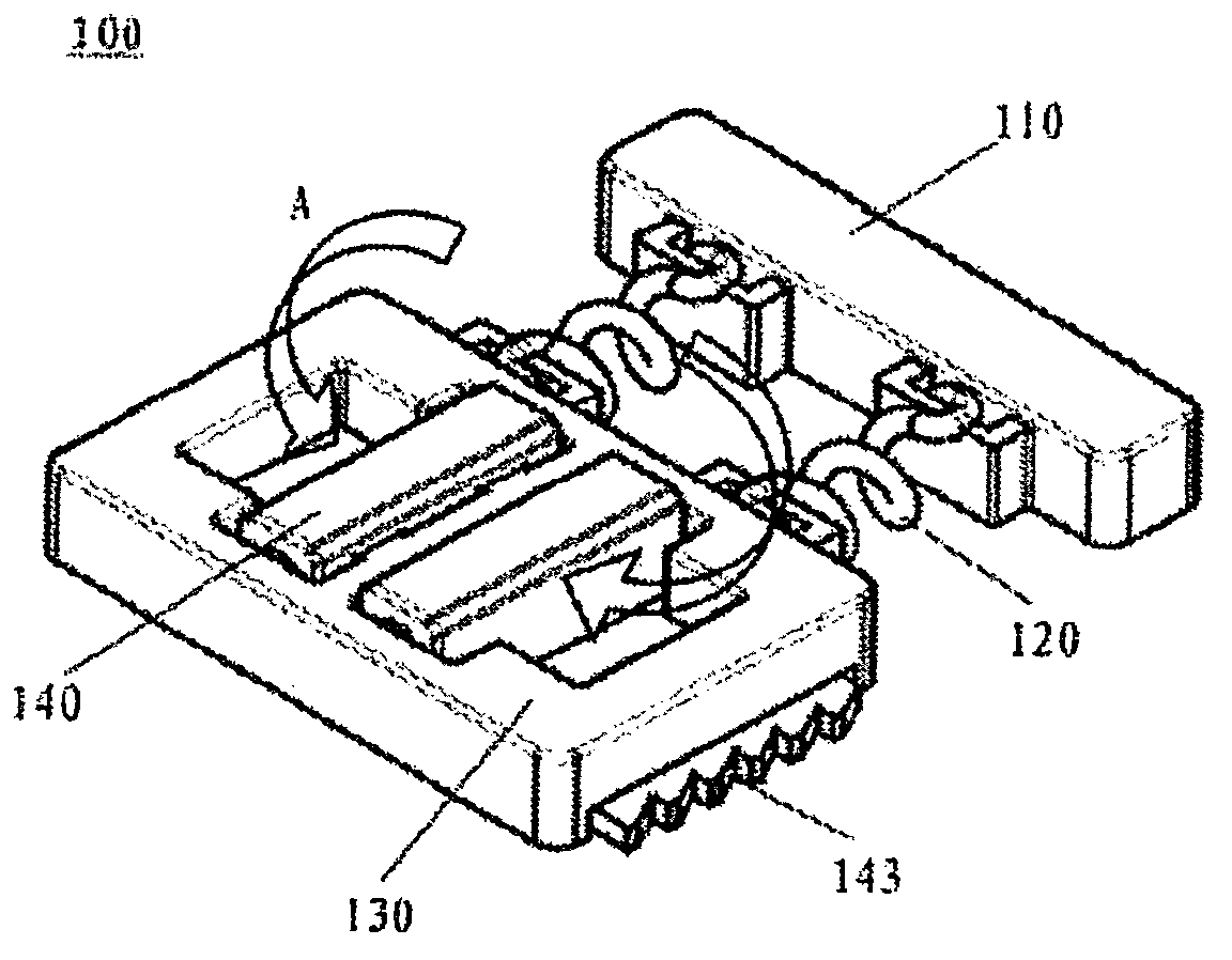
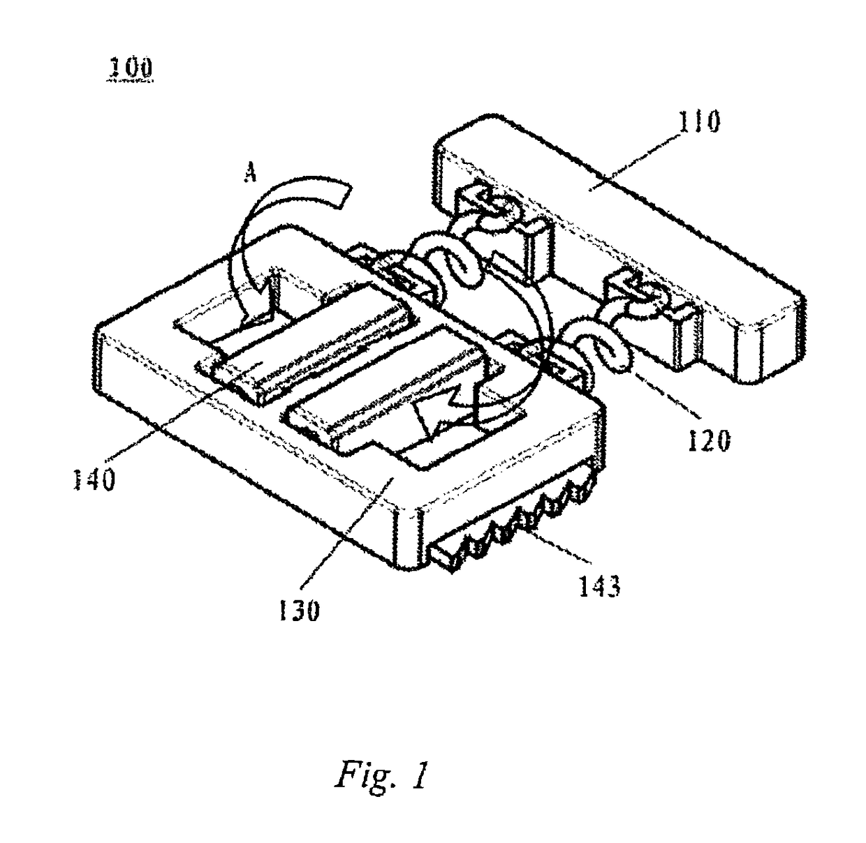
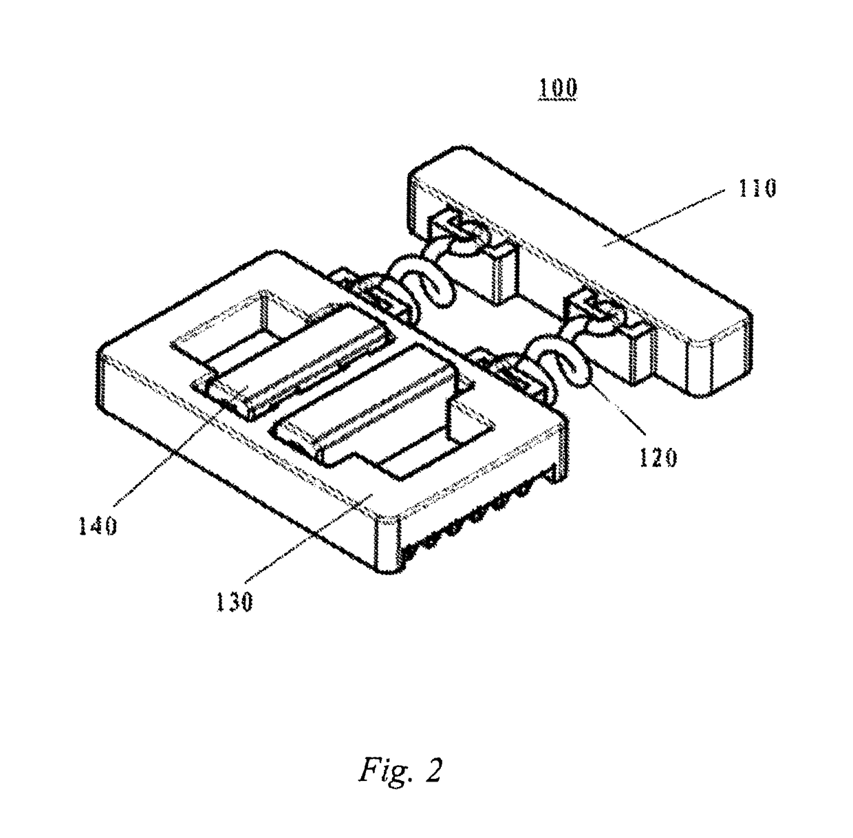
[0033]As shown in FIGS. 1-3, a fastening device 100 in accordance with the present invention comprises a push block 110, a biasing member 120, a housing 130, and a locking member 140 sheathed in the housing 130. The biasing member 120 is positioned between the push block 110 and the housing 130 in a longitudinal direction and is deformable to provide a fastening force. The locking member 140 has a bent structure so as to have elasticity in a transverse direction, and the locking member 140 has tooth-like structures 143 transversely protruding from two sides of the housing 130 in opposite directions. As indicated by the arrows A in FIG. 1, when the locking member 140 is pressed towards the center in the transverse direction, the tooth-like structures 143 can retract into the housing 130, ...


PUM

PropertyMeasurementUnit
fastening forceaaaaaaaaaa
elasticityaaaaaaaaaa
restoring forceaaaaaaaaaa

Abstract

A fastening device and fastening method for fastening a distribution box control panel to a distribution box, the fastening device comprising a push block, a biasing member, a shell, and a locking member sleeved in the shell, wherein the method utilizes the biasing force of the biasing member to fasten the device, and utilizes the elasticity of the locking member having a bending structure to realize assembly and disassembly, where a user can conveniently assemble the device with hand alone, i.e., during assembly, the fastening device is pushed in along a notch in the distribution box control panel and then pressed tightly, and during disassembly, the fastening device can be pushed out after the locking member is pressed such that in comparison to a screw fastening method, the fastening device of the present invention provides a constant fastening force, thus realizing more stable and reliable fastening.

Description

CROSS-REFERENCE TO RELATED APPLICATIONS[0001]This is a U.S. national stage of application No. PCT / CN2012 / 081397 filed 14 Sep. 2012.BACKGROUND OF THE INVENTION[0002]1. Field of the Invention[0003]The present invention relates to a fastening device and a fastening method and, more particularly, to a fastening device and a fastening method for fastening a distribution box control panel to a distribution box.[0004]2. Description of the Related Art[0005]Most control panels for distribution boxes, such as HMI and NC panels, namely human-machine interaction interfaces and numerical control units, require fastening screws for installation to the distribution boxes, and the fastening screws require a specific torque. In this case, when fixing the HMI and NC panel to the distribution box, a user needs to put an installation snap into a grating of the HMI and NC panel and then tighten the screw, ensuring that the product is completely fixed. In order to prevent screw slippage or snap release c...

Claims


Application Information

Patent Timeline
Patent Type & Authority Patents(United States)
IPC IPC(8): H01B7/00H05K7/00H05K7/14F16B2/12H02G3/08H02G3/14H02B1/044H05K5/00E05C19/06F16B2/22
CPCH05K7/1417F16B2/12F16B2/22H02G3/08H02G3/14H02B1/044Y10T29/49947Y10T24/4465H02B1/26
Inventor ZHU, YU HAO
Owner SIEMENS AG
Learn More