Air transmission system for flexible passenger supply units

a passenger supply and air transmission technology, applied in the direction of aircraft crew accommodation, transportation and packaging, air-treatment apparatus arrangement, etc., can solve the problems of limiting the flexibility of the cabin configuration, hammer installation in the cabin equipment and retrofitting, etc., and achieve the effect of easy adjustmen

Active Publication Date: 2017-12-05
AIRBUS OPERATIONS GMBH
View PDF19 Cites 0 Cited by
  • Summary
  • Abstract
  • Description
  • Claims
  • Application Information

AI Technical Summary

Benefits of technology

[0005]An aspect of the invention may provide an air supply system that can be easily adjusted to a modified seat layout.
[0008]The air supply system enables a distribution of individual air panels without having to specially adjust the individual air supply. A flexible interface between the individual air panels and aircraft air supply system or climate control system permits an individual air supply at any longitudinal coordinate of the aircraft cabin. An operator thus has the option of selecting any seat spacing configuration desired, without having to reposition the supply channel. Instead, he or she can simply shift the individual air panels or give them a staggered arrangement.
[0011]According to an embodiment, each of the magnetic valves may comprise a closing element which is adapted to move substantially along a central axis of the outlet opening, between a closed position and an open position. To further improve a closing of an outlet opening, the air outlet may comprise a first contact surface and the magnetic valve may comprise a closing element with a second contact surface, wherein the first contact surface and the second contact surface are correspondingly inclined relative to a central axis of the air outlet opening. With such a structure, each closing element of the valve will easily find the air outlet opening so as to reliably close it.

Problems solved by technology

However, the problem in such air distribution systems is that the air showers or air nozzles must be adjusted to the respective seat positions, which significantly hampers installation in the cabin equipment and retrofitting.
This greatly limits the flexibility of the cabin configuration, since the aircraft reference documentation and connecting points must be determined very early on in the definition process.

Method used


Image

  • Air transmission system for flexible passenger supply units
  • Air transmission system for flexible passenger supply units
  • Air transmission system for flexible passenger supply units

Examples


Embodiment Construction

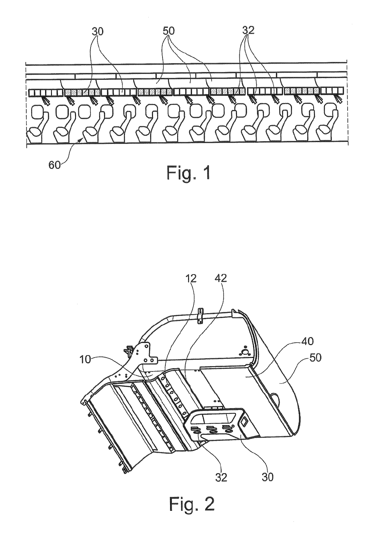
[0028]FIG. 1 shows a longitudinal section through a passenger cabin of an aircraft. A plurality of seat rows 60 are arranged in the passenger cabin. Situated over the seat rows are hat racks or storage compartments 50 along with passenger supply units 30 to supply the passengers with signals, information, electrical or electronic connections, as well as fresh air. As depicted on FIG. 1, air nozzles 32 allocated to each individual seat row are provided, and situated on a passenger supply channel spaced a corresponding distance apart from each other.

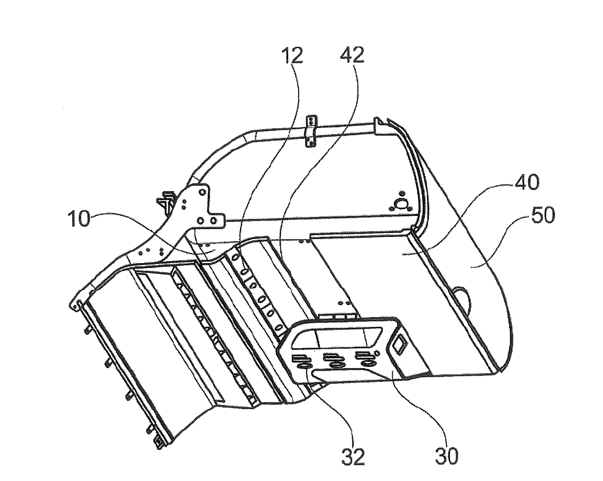
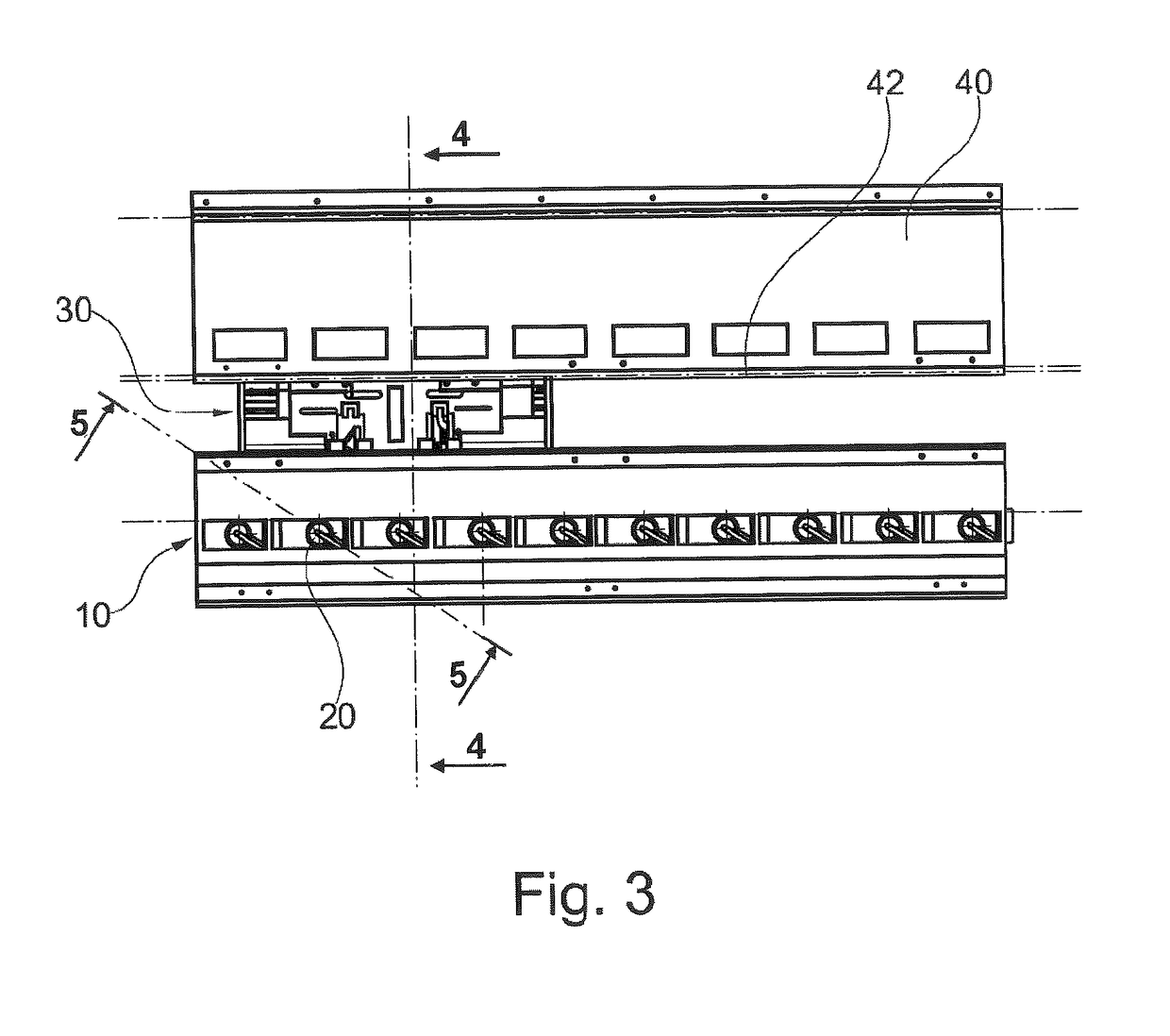
[0029]FIG. 2 is an isometric view of a storage compartment 50, wherein cladding elements 40 are provided under the storage compartment. In roughly the middle under the storage compartment, the cladding elements 40 form a recess with a sliding rail 42 suitable for accommodating at least one passenger supply unit (PSU) 30. An air supply line 10 is located on one side of the recess. The air supply line 10 has at least one air outlet opening 1...


PUM


Abstract

An air supply system for passengers includes an air supply line with a plurality of laterally situated air outlets, an individual air panel with at least one air nozzle and an air inlet opening. The individual air panel can be variably positioned along the air supply line in such a way that the air inlet opening faces one of the air outlets. A plurality of magnetic valves is arranged at the air outlets of the air supply line. One of the magnetic valves may be magnetically actuated by the individual air panel, when the air inlet opening of the individual air panel faces said one magnetic valve, so that air can flow out of the air supply line through the air outlet and the air inlet opening to the air nozzle.

Description

FIELD OF THE INVENTION[0001]The invention relates to an air supply system for passengers in a passenger compartment, for example of an aircraft. In particular, the invention relates to a system for transmitting air in passenger supply units (passenger supply unit / PSU), which can be flexibly arranged relative to a central air supply line.BACKGROUND OF THE INVENTION[0002]DE 10 2010 012 882 B3 shows a system for supplying individual air with an air line and a sliding individual air panel. The air line has a tubular element with a slotted opening formed in the longitudinal direction, and a lamellar element, which is suitable for closing the slotted opening. The individual air panel has a housing, an air nozzle for controlling individual air on the front side of the housing, and a cantilever arm on the rear side of the housing for displacing the lamellar element, and thereby partially opening the air line, as well as an opening for receiving air from the air line.[0003]Described in DE 10...

Claims


Application Information

Patent Timeline
Patent Type & Authority Patents(United States)
IPC IPC(8): B64D13/00B64D11/00
CPCB64D13/00B64D11/00B64D2013/003
Inventor SCHNEIDER, UWEBERGER, VLADIMIRWIETZKE, ANDREAS
Owner AIRBUS OPERATIONS GMBH
Why Eureka
Try Eureka