
Image quality enhancing apparatus, image display apparatus, image quality enhancing method, and computer readable storage medium

a technology of image quality and enhancing method, applied in image enhancement, image analysis, instruments, etc., can solve the problems of image quality degrade, image quality decline, and resolution decline, so as to reduce the amount of processes, reduce the processing time necessary for the calculation of coefficients, and delay the effect of the process

Active Publication Date: 2017-12-05
EIZO
View PDF11 Cites 2 Cited by
  • Summary
  • Abstract
  • Description
  • Claims
  • Application Information

AI Technical Summary

Benefits of technology

[0034]In the present invention, the image quality enhancing apparatus is able to reduce the amount of processes which calculate a sparse solution of the coefficient for expressing the feature quantity of the image with a linear sum of the first feature quantities. For this reason, the processing duration necessary for the calculation of the coefficient shortens, and a delay in the process by the image quality enhancement of an image decreases even when a real-time performance is required. Therefore, the present invention has a superior effect that a learning-type image quality enhancing method which utilizes a sparse expression becomes sufficiently practical, etc.

Problems solved by technology

When the pixel count is simply increased to enlarge the image, a problem that the resolution decreases and the image quality degrades occurs.
The degradation of an image quality occurs by a downsampling or enlarging, and this degradation of the image quality occurs in a high frequency component of the luminance.
However, there is no guarantee that the solution of the α obtained here is a sparse solution.
However, also in this case, there is no guarantee that a sparse solution of a can be obtained.
A differentiation of L1 norm is generally difficult, and solving Equation (1) analytically is difficult.

Method used


Image

  • Image quality enhancing apparatus, image display apparatus, image quality enhancing method, and computer readable storage medium
  • Image quality enhancing apparatus, image display apparatus, image quality enhancing method, and computer readable storage medium
  • Image quality enhancing apparatus, image display apparatus, image quality enhancing method, and computer readable storage medium

Examples


embodiment 1

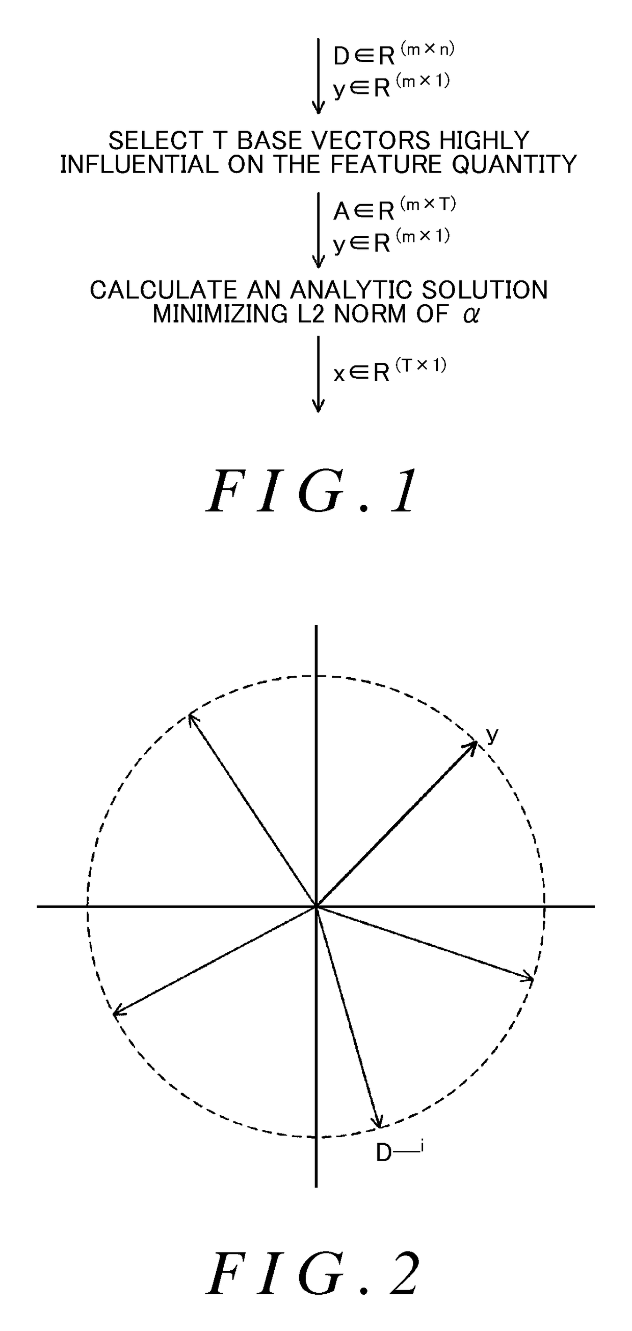
[0058]In the present embodiment, a sparse solution of a coefficient matrix α is calculated without using the iteration method. FIG. 1 is a conceptual diagram showing an outline of the method of calculating the sparse solution of the coefficient matrix α in Embodiment 1. In the present embodiment, T base vectors that are highly influential on the feature quantity of an image are selected from among n base vectors recorded in dictionary data. Here, T

[0059]FIG. 2 is a schematic view which expresses conceptually the relationship between the feature quantity y of an image and a plurality of base vectors. Matrix D with m lines and n columns is a matrix in which n base vectors D_i (i=1 to n) consisting of m elements are aggregated, and the feature quantity y is a vector consisting o...

embodiment 2

[0079]In Embodiment 2, an embodiment where the number of base vectors which express the feature quantity of an image with a linear sum is adjusted is shown. In Embodiment 1, the number of the base vectors with non-zero coefficients, T, is regarded as a constant value. In a method to solve a conditional equation of Equation (1) by the iteration method described in Non-Patent Document 1, the number of the base vectors with non-zero coefficients varies according to the position of the patch in an image. Specifically, the number of the base vectors increases in a portion of an edge in the image. Therefore, in the portions other than the edge portion, it is possible to decrease the number of base vectors. Also, when there is a lot of noise in the image, the larger the number of the base vectors, the easier it becomes for the linear sum of the base vectors to express the noise and the easier it becomes for the noise to reappear also in an image with the image quantity enhanced. Therefore,...

embodiment 3

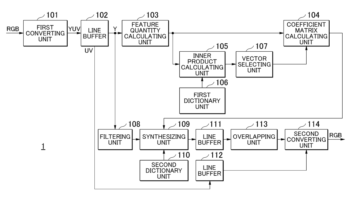
[0090]The configuration of the image display apparatus according to Embodiment 3 is similar to that of Embodiment 2. FIG. 11 is a block diagram showing the configuration of internal functions of the image quality enhancing apparatus 1 according to Embodiment 3. The image quality enhancing apparatus 1 does not comprise the inner product calculating unit 105 and the vector selecting unit 107, the vector-count calculating unit 115 is connected to the coefficient matrix calculating unit 104, and the first dictionary unit 106 is connected to the coefficient matrix calculating unit 104.

[0091]The vector-count calculating unit 115 calculates the number of the base vectors T with non-zero coefficients by a method similar to that of Embodiment 2. Namely, the vector-count calculating unit 115 calculates the number of the base vectors T based on the value of which has been input from the control unit 2 or the noise standard deviation of the patch. The vector-count calculating unit 115 inputs th...


PUM


Abstract

An image quality enhancing apparatus which make a learning-type image quality enhancing method utilizing a sparse expression practical are provided. The apparatus calculates, from the feature quantity of an image, coefficients of low-image-quality base vectors expressing a feature quantity with a linear sum and generates the image with the image quality enhanced by calculating a linear sum of high-image-quality base vectors using the calculated coefficient. When calculating the coefficient, the number of base vectors with non-zero coefficients is determined, the determined number of base vectors is selected, and a solution of a coefficient matrix is calculated by assuming the coefficients of the base vectors other than the selected base vectors are zero. The amount of processes necessary for obtaining a sparse solution of a coefficient matrix can be reduced by adjusting the number of base vectors with non-zero coefficients, and a practical image quality enhancing apparatus can be realized.

Description

[0001]The contents of the following patent applications are incorporated herein by reference: No. JP2013-228770 filed on Nov. 1, 2013 and No. PCT / JP2014 / 078845 filed on Oct. 30, 2014.BACKGROUND[0002]1. Technical Field[0003]The present invention relates to an image quality enhancement method of an image, more specifically, an image quality enhancing apparatus, an image display apparatus, an image quality enhancing method, and a computer readable storage medium, which execute a learning-type image quality enhancing method utilizing sparse expression.[0004]2. Related Art[0005]An image is sometimes enlarged when handling an image such as when displaying an image, etc. When the pixel count is simply increased to enlarge the image, a problem that the resolution decreases and the image quality degrades occurs. In order to solve this problem, a technique to enhance an image quality of an image is being developed. For example, a technique of a learning-type super-resolution is being develope...

Claims


Application Information

Patent Timeline
Patent Type & Authority Patents(United States)
IPC IPC(8): G06K9/40G06T3/40H04N7/01G06T5/00G06T5/40
CPCG06T3/4076G06T3/4053G06T5/001G06T5/003H04N7/0117G06T5/40G06T2207/20221G06T2207/20024G06T2207/20081G06T2207/20192G06T5/00
Inventor HIGASHI, MASAFUMICHEN, HAIFENGAOKI, REOMATSUZAKI, HIROKIKATAGIRI, TADAYOSHI
Owner EIZO
Learn More