Rigid slit-tube laminate system

a laminate system and slit tube technology, applied in mechanical equipment, chemistry equipment and processes, other domestic objects, etc., can solve the problems of insufficient resistance to torsional deflection, insufficient resistance, insufficient resistance to deflection, etc., to avoid or reduce the fraying or detachment of fibers

Active Publication Date: 2017-12-12
TENDEG
View PDF56 Cites 7 Cited by
  • Summary
  • Abstract
  • Description
  • Claims
  • Application Information

AI Technical Summary

Benefits of technology

[0007]Accordingly, a broad object of the invention can be to provide a laminate structure and a method of making the laminate structure which avoids or reduces fraying or detachment of fibers at the laminate edges.
[0008]Another broad object of the invention can be to provide a laminate structure and a method of making a laminate structure which in the form of a longitudinally slit tube has, as compared to conventional laminate structures, one or more of reduced deflection along the longitudinal axis under load, reduced radial surface deflection under radial load (increased buckling resistance) or reduced torsional deflection about the central longitudinal axis.

Problems solved by technology

Additionally, because longitudinally slit tubes often deploy from a first condition in the form of flat laminate extended from a roll or coil to assume a second condition in the form of a longitudinally slit tube, the tubular form may not have adequate resistance to deflection along the longitudinal axis under load, or may not have adequate resistance to radial surface deflection upon application of radial forces, or may not have adequate resistance to torsional deflection of the tubular form due applied torque or twisting about the central longitudinal axis of the tubular form.

Method used


Image

  • Rigid slit-tube laminate system
  • Rigid slit-tube laminate system
  • Rigid slit-tube laminate system

Examples


Embodiment Construction

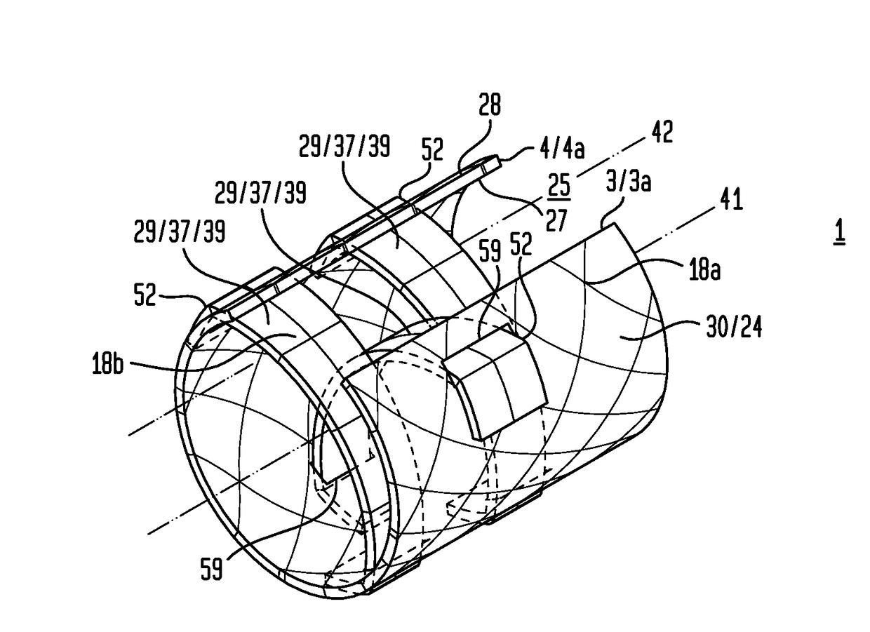
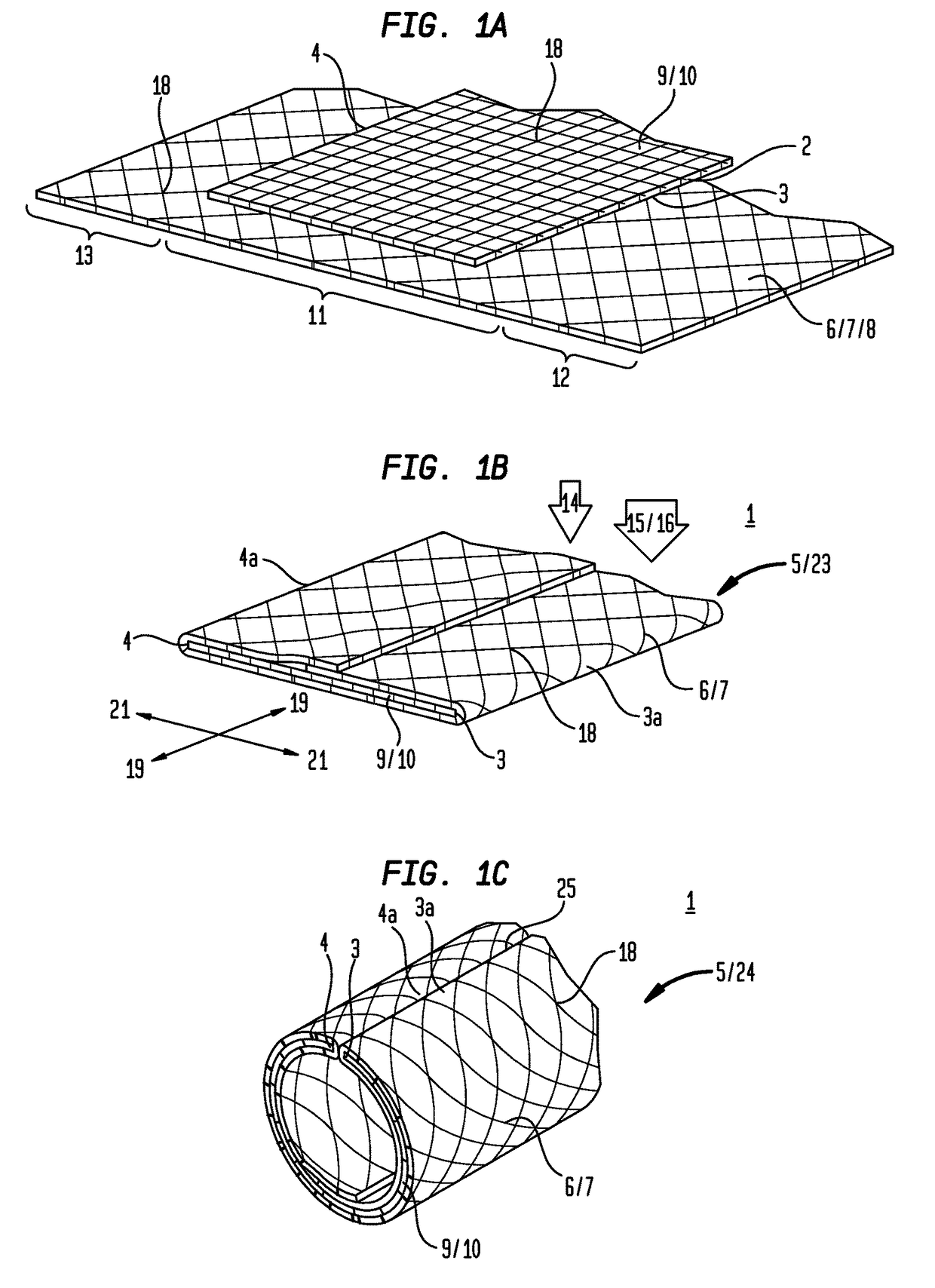
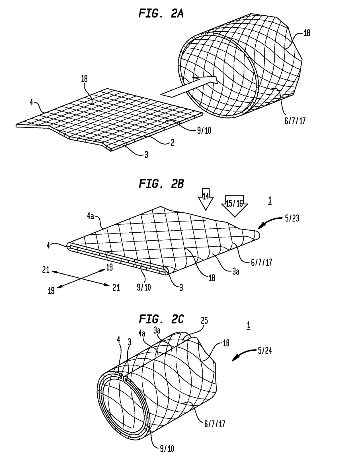
[0019]Now referring primarily to FIGS. 1A through 1C and 2A through 2C, particular embodiments of an inventive laminate structure (1) are shown which avoid or reduce fraying or detachment of one or more fibers (2) from a first laminate edge (3) or a second laminate edge (4) or other edge of a laminate (5).

[0020]With respect to the illustrative embodiment shown in FIGS. 1A through 1C, a first laminable material (6) having one or more layers (7), as above described, can be disposed in a substantially flat unfolded condition (8) (as shown in the example of FIG. 1A). A second laminable material (9) having one or more layers (10) can be engaged to a medial portion (11) of the first laminable material (6) disposed in the flat unfolded condition (8) defining remaining first and second end portions (12)(13) of said first laminable material (6).

[0021]The first end portion (12) of the first laminable material (6) can be folded proximate the first laminate edge (3) of the second laminable mate...


PUM

PropertyMeasurementUnit
pressureaaaaaaaaaa
pressureaaaaaaaaaa
angleaaaaaaaaaa

Abstract

Laminate structures and methods of making laminate structures having overwrapped laminate edges which resist delamination and fraying or including one or more stabilizer laminates which afford greater radial and torsional rigidity in longitudinally slit tube structures.

Description

[0001]This application is the United States National Stage of International Patent Cooperation Treaty Patent Application No. PCT / US2013 / 071266, filed Nov. 21, 2013, which claims the benefit of U.S. Provisional Patent Application No. 61 / 729,129, filed Nov. 21, 2012, each hereby incorporated by reference herein.I. TECHNICAL FIELD[0002]Laminate structures and methods of making laminate structures having overwrapped laminate edges which resist delamination and fraying or including one or more stabilizer laminates which afford greater radial and torsional rigidity in longitudinally slit tube structures.II. BACKGROUND[0003]Laminates can be constructed by uniting two or more layers of material together. The process of creating a laminate conventionally refers to impregnating or applying an adherent material in or between layers of laminable material and treating the stack of laminable material to sufficient heat or pressure to join the layers of laminable material. The resulting laminate c...

Claims


Application Information

Patent Timeline
Patent Type & Authority Patents(United States)
IPC IPC(8): F16L55/00B32B5/26B32B1/08B32B3/04B32B7/12F16L11/04B32B3/26B32B3/02B29C67/00B29C61/00B32B37/14
CPCB32B3/266B29C61/00B29C67/0014B32B1/08B32B3/02B32B3/04B32B7/12F16L11/042B32B5/26B32B2597/00B32B37/142B32B2260/021B32B2260/046
Inventor FRANCIS, WILLIAM H.FREEBURY, GREGG E.HULSE, MICHAEL J.
Owner TENDEG
Why Eureka
Try Eureka