
Smart security device with monitoring mode and communication mode

Active Publication Date: 2017-12-19
INVENT LY LLC
View PDF48 Cites 20 Cited by
  • Summary
  • Abstract
  • Description
  • Claims
  • Application Information

AI Technical Summary

Benefits of technology

The present invention is a device that has a processor, an energy source, sensors, and a wireless transceiver. It also has a memory that can select between low-power and high-power modes of operation. In the low-power mode, the device consumes less power and has limited functionality, while in the high-power mode, it consumes more power and has more functionality. The device can also activate the wireless transceiver to send information from the sensors to a remote device. The technical effect of this invention is to allow the device to conserve power and have limited functionality in low-power mode, while still being able to activate the wireless transceiver and have full functionality in high-power mode.

Problems solved by technology

These rapidly expanding networks consume a tremendous amount of power, which is typically supplied from traditional electrical power grids.
However, current self-powered devices, such as devices that obtain energy from solar power, typically waste much of their power communicating with other networked computing devices.
Such an installed base of sensors creates issues such as powering such sensors as well as transporting and storing the data received from the sensors.
Such conventional approaches are unlikely to be sufficient with the grand vision of the “Internet of Things”.
The communications bandwidth (and data storage on the Internet to implement such an approach) could include hundreds of times as many sensors as conventional smartphones, potentially consuming the highest amount of energy of the Internet.
If scaled to a trillion sensors, a huge number of devices would need to be implemented with batteries that would be unaffordable (or at least inconvenient) to change.
A huge amount of traffic on already congested networks would further increase the power needs of each device, since higher antenna output would likely be needed to overcome interference and noise.

Method used


Image

  • Smart security device with monitoring mode and communication mode
  • Smart security device with monitoring mode and communication mode
  • Smart security device with monitoring mode and communication mode

Examples


Embodiment Construction

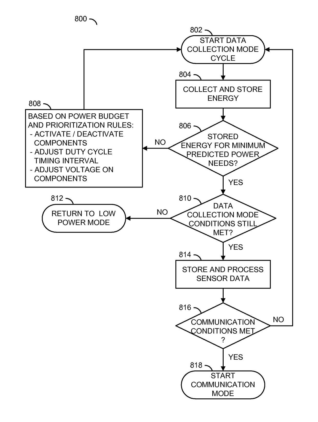
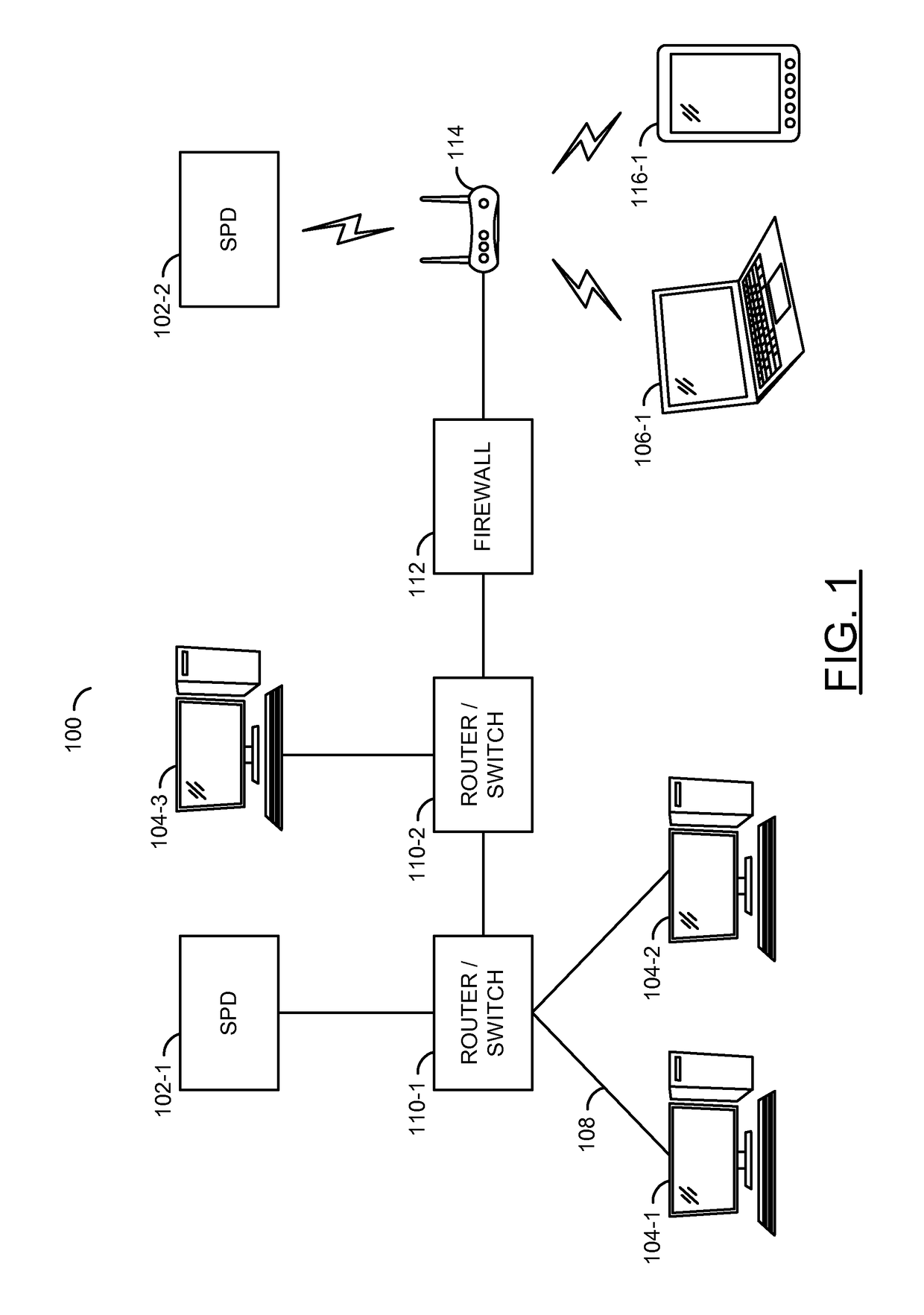
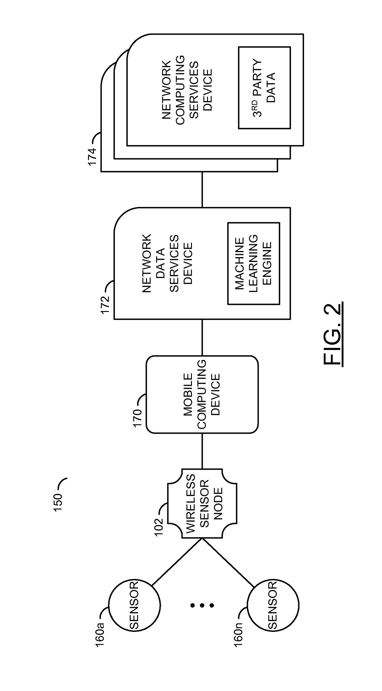
[0033]Embodiments of self-powered systems, devices, and methods are described herein. The self-powered system may include a computing device that selectively communicates with a self-powered device. The self-powered device may include: a circuit to power the self-powered device; memory; a processor; and a program mechanism that is stored in the memory for execution by the processor. The program mechanism may include instructions for selecting one of a plurality of modes of operation, including a first mode of operation in which the self-powered device consumes less than a pre-determined amount of power and a second mode of operation in which self-powered device consumes more than the pre-determined amount of power. (See FIG. 17).

[0034]Embodiments of the invention provide a context-aware and / or power-aware wireless sensor network system that enables application needs to determine which data is captured, transmitted and / or stored at the edge of the wireless sensor network. Such an imp...


PUM


Abstract

A device comprising a processor, an energy source, one or more sensors, a wireless transceiver and a memory. The memory may comprise instructions for selecting one of a plurality of modes of operation. The modes of operation may comprise (i) a low-power mode in which the device consumes less than a pre-determined or an adaptively-determined amount of power and the device has less than full functionality and (ii) a high-power mode in which the device consumes more than the pre-determined or the adaptively-determined amount of power and the device has more functionality than in the low-power mode. The instructions for selecting one of the modes of operation may comprise (i) instructions for conserving power by transitioning from the high-power mode to the low-power mode and (ii) instructions for activating the wireless transceiver to transmit a message with information from the sensors to a remote device.

Description

[0001]This application relates to U.S. Ser. No. 14 / 169,464, filed Jan. 31, 2014, which relates to U.S. Ser. No. 14 / 103,209, filed Dec. 11, 2013, which relates to U.S. Ser. No. 13 / 946,414, filed Jul. 19, 2013, now U.S. Pat. No. 8,850,242, which relates to U.S. Ser. No. 13 / 406,469, filed Feb. 27, 2012, now U.S. Pat. No. 8,516,279, which relates to U.S. Ser. No. 12 / 472,327, filed May 26, 2009, now U.S. Pat. No. 8,127,158, which relates to U.S. Ser. No. 11 / 443,668, filed May 30, 2006, now U.S. Pat. No. 7,539,882, which relates to U.S. Provisional Application No. 60 / 685,976, filed May 30, 2005. This application also relates to U.S. Ser. No. 14 / 090,099, filed Nov. 26, 2013. Each of the mentioned applications are hereby incorporated by reference in their entirety.FIELD OF THE INVENTION[0002]The embodiments disclosed herein relate to power management in self-powered electronic devices, and, in particular, to predictive power management in self-powered electronic devices that include power s...

Claims


Application Information

Patent Timeline
IPC IPC(8): G06F1/32G06F1/26
CPCG06F1/3296G06F1/266G06F1/26G06F1/3206G06F1/324Y02D10/00
Inventor BROWN, STEPHEN J.MEADE, DAYLYN M.FLOOD, TIMOTHY P.HALLATT, CLIVE A.JESSUP, HOLDEN D.
Owner INVENT LY LLC
Learn More