Footing plates

a technology of footings and plates, applied in the direction of protective foundations, bulkheads/piles, buildings, etc., can solve the problems of time-consuming and costly approaches, large amount of labour and materials required to provide secure footings for posts or poles, and large holes in the ground, so as to achieve quick and cost-effective

Active Publication Date: 2017-12-26
SUREFOOT IP HLDG PTY LTD
View PDF24 Cites 20 Cited by
  • Summary
  • Abstract
  • Description
  • Claims
  • Application Information

AI Technical Summary

Benefits of technology

[0005]The said downwardly extending flange or flanges may be formed by bending the planar web adjacent its edges or by welding of the flanges to the edges of the planar web. Alternatively, the flange or flanges and planar web may be cast or moulded as one piece. The provision of flanges stiffens the planar web to minimize bending or warping thereof. It will be appreciated that the planar web and flanges will be of sufficient thickness to permit the footing plate to be usefully employed in supporting the retaining means for receiving a post, pole or upright structural beam without being distorted appreciably.
[0012]The present invention provides a relatively quicker and more cost effective way to erect posts or poles of any reasonable given size without the need to excavate large holes and use considerable quantities of cement or concrete.

Problems solved by technology

However, depending on the size and / or purpose of the building or structure, significant amounts of labour and materials are required to provide secure footings for the posts or poles.
One approach is to dig excessively large holes, place the lower ends of the posts or poles in the holes and fill the holes with concrete or cement.
These approaches are time consuming and costly.
Swelling and / or contraction of the concrete or cement can occur, necessitating further time and cost to correctly secure the footing.

Method used


Image

  • Footing plates
  • Footing plates
  • Footing plates

Examples


Embodiment Construction

[0014]In order that the invention may be more clearly understood some preferred embodiments are hereinafter described with reference to the accompanying drawings in which:

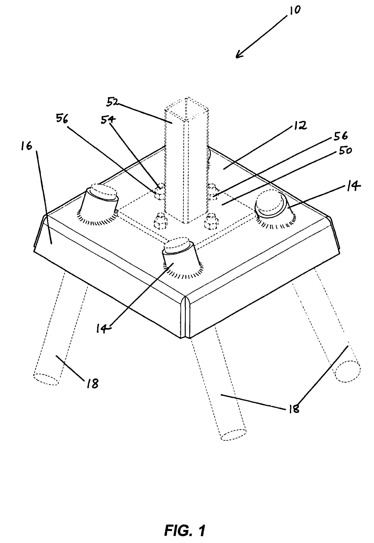
[0015]FIG. 1 is a perspective view of a first preferred embodiment with a socket (in phantom) secured thereto and pins (in phantom);

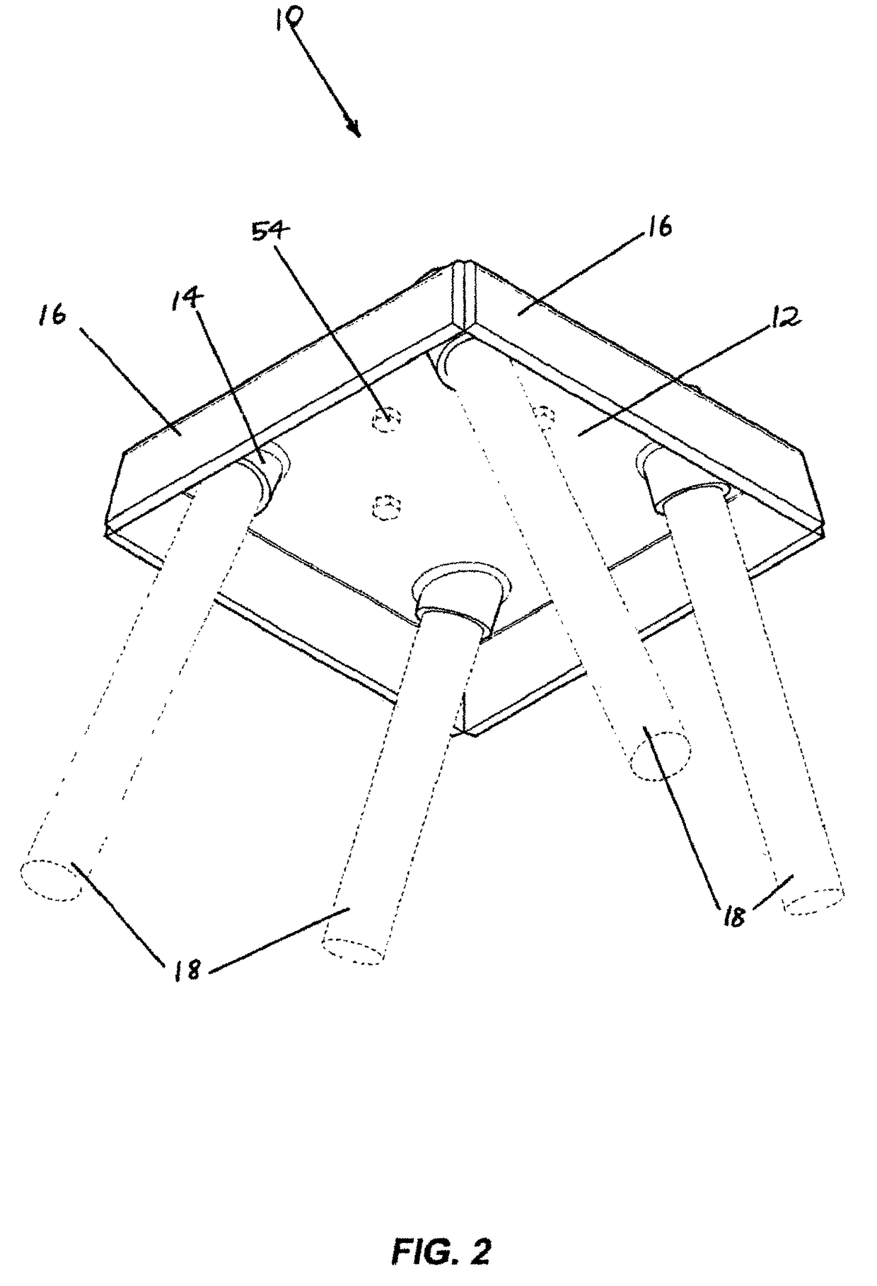
[0016]FIG. 2 is an underneath perspective view of the embodiment of FIG. 1;

[0017]FIG. 3 is an elevational view of the embodiment of FIG. 1;

[0018]FIG. 4 is a plan view from above of the embodiment of FIG. 1;

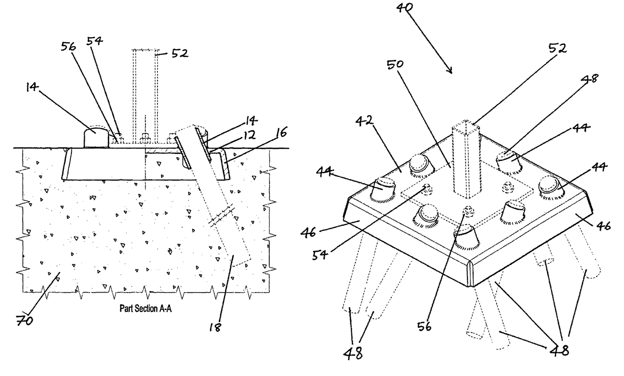
[0019]FIG. 5 is a partial sectional view along line A-A of FIG. 4 (showing the first embodiment in use);

[0020]FIG. 6 is a perspective view of a second preferred embodiment showing a socket and pins in phantom;

[0021]FIG. 7 is an underneath perspective view of the embodiment of FIG. 6;

[0022]FIG. 8 is an elevational view of the embodiment of FIG. 6;

[0023]FIG. 9 is a plan view from above of the embodiment of FIG. 6;

[0024]FIG. 10 is a sectional view along line A-A of FIG. 9;

[0025]FIG. 11 ...


PUM


Abstract

A footing plate (10) including a planar web (12) through or from which a plurality of tubes (14) pass, the tubes (14) being adjacent to the edges of the planar web (12) and being disposed at angles to the planar web (12), none of the angles being 90°, the tubes (14) being sized to permit the passage therethrough of pins (18) for fixing into underlying ground, the upper face of the planar web (12) optionally being provided with a plurality of holes to accept bolts for retaining means to receiving a post, pole or upright structural beam, the planar web (12) also being provided with a downwardly extending flange (16) from at least one of the edges of the planar web (12).

Description

FIELD OF THE INVENTION[0001]This invention relates to the provision of footings for posts or beams in buildings and structures. In particular this invention relates to improved footing plates for posts, poles or upright beams in buildings and similar structures.BACKGROUND OF THE INVENTION[0002]Posts and poles are commonly used integers in buildings and similar structures. However, depending on the size and / or purpose of the building or structure, significant amounts of labour and materials are required to provide secure footings for the posts or poles. One approach is to dig excessively large holes, place the lower ends of the posts or poles in the holes and fill the holes with concrete or cement. Another approach is to dig large holes, fill them with concrete or cement, insert bolts into the concrete or cement, and then retain footing plates on the bolts. These approaches are time consuming and costly. Swelling and / or contraction of the concrete or cement can occur, necessitating f...

Claims


Application Information

Patent Timeline
Patent Type & Authority Patents(United States)
IPC IPC(8): E02D27/42E02D31/00E02D5/80E04H12/22
CPCE02D27/42E04H12/223E02D31/002E02D5/80E04H12/22
Inventor DESPOTELLIS, NEIL
Owner SUREFOOT IP HLDG PTY LTD
Why Eureka
Try Eureka