Fuel supply device

a fuel supply and fuel technology, applied in the direction of liquid fuel feeders, machines/engines, transportation and packaging, etc., can solve the problem of limited fuel supply loss, achieve the effect of simplifying the structure, limiting the fuel supply loss, and ensuring the performance of the internal combustion engin

Active Publication Date: 2017-12-26
AISAN IND CO LTD
View PDF14 Cites 3 Cited by
  • Summary
  • Abstract
  • Description
  • Claims
  • Application Information

AI Technical Summary

Benefits of technology

[0007]The present disclosure is made in view of the above disadvantages. Thus, it is an objective of the present disclosure to provide a fuel supply device that can achieve both of the energy saving and ensuring of the required performance of the internal combustion engine.
[0009]At the diffuser passage, which draws the accumulate fuel from the fuel tank through the discharge of the fuel from the nozzle passage, the flow outlet opened toward the latera side discharges the fuel flow into the sub-tank, and this fuel flow is swirled by the swirling wall structure of the first aspect. Specifically, the fuel flow, which is outputted from the flow outlet, is bent along the curved wall surface that is curved about the longitudinal axis that extends from the lower side to the upper side of the sub-tank, and then this fuel flow makes the U-turn along the U-turn wall surface that extends continuously from the curved wall surface. Thereby, the fuel flow is swirled. In this way, the air bubbles, which are contained in the fuel and have the small specific gravity, are concentrated in the center part of the swirl flow to form a cluster of air bubbles in a manner that increases a buoyant force of the air bubbles. Thereby, movement of the cluster of air bubbles is less likely interfered by the swirling wall structure that extends from the lower side to the upper side in the sub-tank. Furthermore, in the sub-tank, which is shaped into the tubular body that has the bottom, an opening of the sub-tank, through which the jet pump and the fuel pump are insertable into the inside of the sub-tank, opens toward the upper side. Therefore, the cluster of air bubbles can be easily expelled by the upward movement of the cluster of air bubbles. Furthermore, the fuel, which is received in the sub-tank and from which the air bubbles are removed by the swirling wall structure, can be entirely drawn into and discharged from the fuel pump toward the internal combustion engine. Thereby, the supply loss of the fuel can be limited.
[0010]According to the first aspect of the present disclosure, in addition to the energy saving, which is implemented by limiting the supply loss of the fuel, the required performance of the internal combustion engine can be achieved by the removal of the air bubbles.
[0012]According to the second aspect, the fuel flow, which is outputted from the second jet pump, is merged with the fuel flow, which is outputted from the flow outlet of the first jet pump and is swirled by the swirling wall structure, through the confluence opening to form the swirl flow. Therefore, it is possible to remove the air bubbles from the fuel, which is pumped by the first jet pump from the location on the lower side of the sub-tank, and also the air bubbles from the fuel, which is pumped by the second jet pump from the other location that is other than the location on the lower side of the sub-tank. Thereby, the swirling wall structure, which removes the air bubbles and limits supply loss of the fuel, is commonly used by the first jet pump and the second jet pump to simplify the structure and to achieve both of the energy saving and the required performance of the internal combustion engine.

Problems solved by technology

Thereby, the supply loss of the fuel can be limited.

Method used


Image

  • Fuel supply device
  • Fuel supply device
  • Fuel supply device

Examples


first embodiment

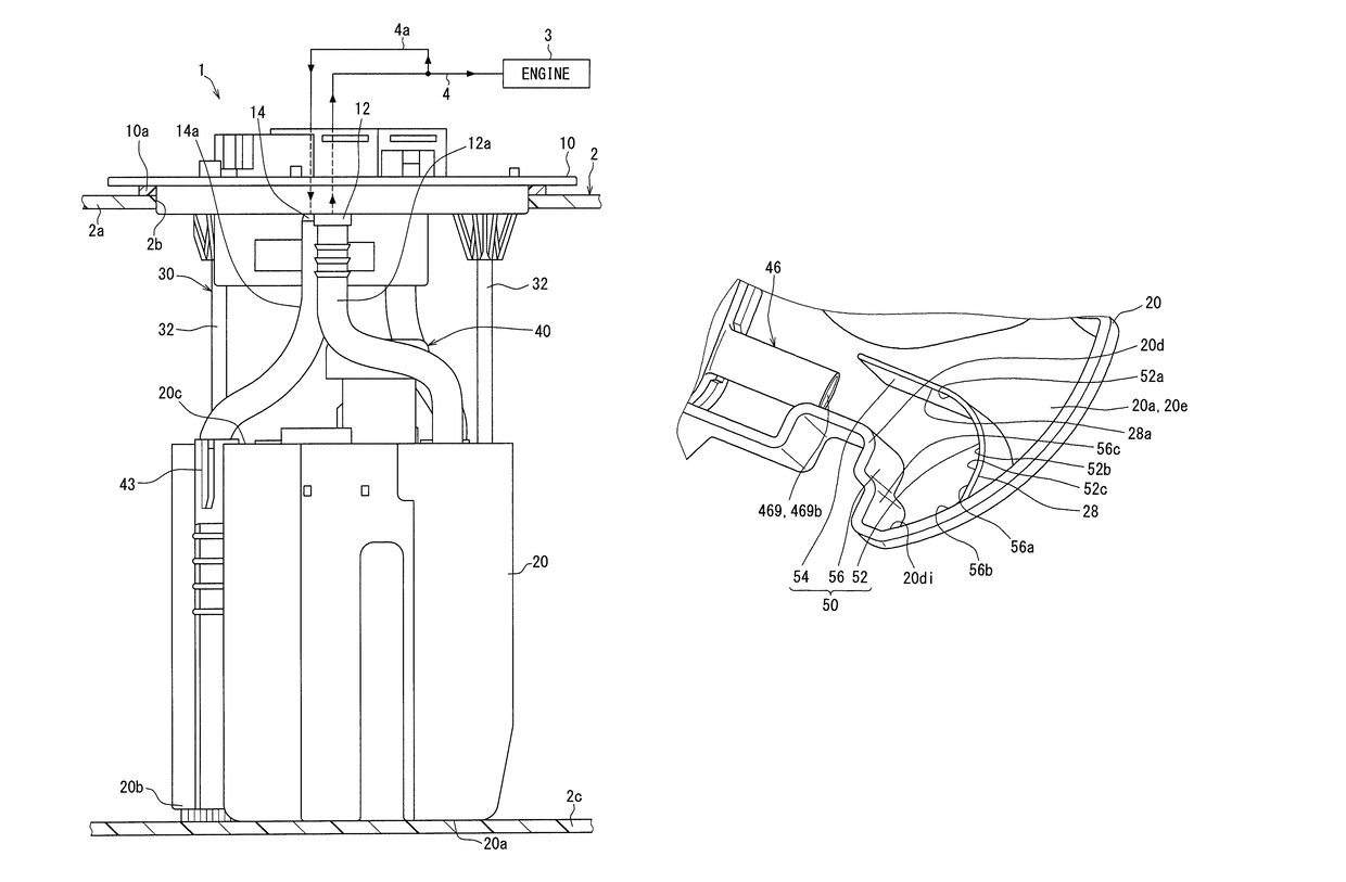
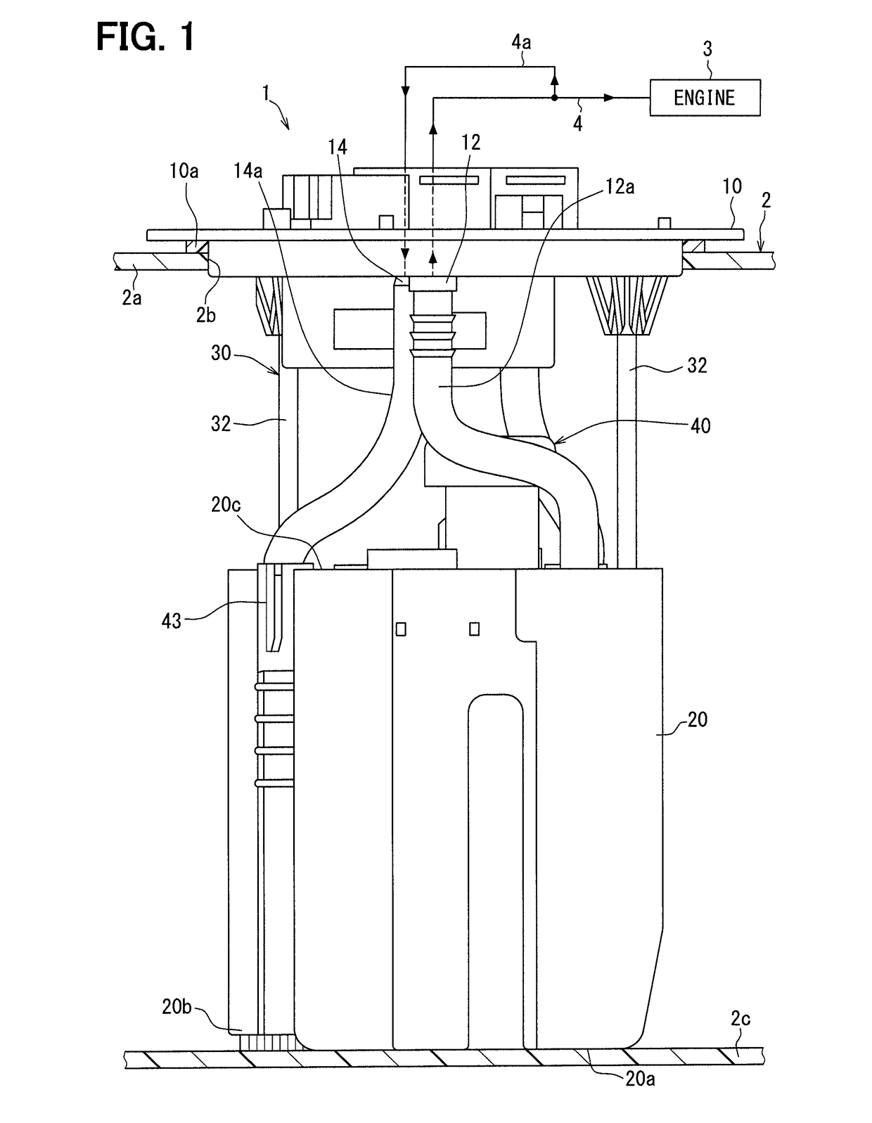
[0038]As shown in FIG. 1, a fuel supply device 1 according to a first embodiment of the present disclosure is installed in a fuel tank 2 of a vehicle. The device 1 supplies fuel, which is stored in the fuel tank 2, to fuel injection valves of an internal combustion engine 3 indirectly through another intervening device, such as a high pressure pump, or directly without through such an intervening device. The fuel tank 2, in which the device 1 is installed, is made of resin or metal and is shaped into a hollow form to accumulate the fuel to be supplied to the internal combustion engine 3. The internal combustion engine 3, to which the fuel is supplied from the device 1, may be a diesel engine or a gasoline engine. In FIGS. 1 and 3-6, a top-to-bottom direction and a transverse direction respectively coincide with a vertical direction and a horizontal direction of the vehicle placed on a horizontal plane (hereinafter, simply referred to as a vertical direction and a horizontal directio...

second embodiment

[0078]As shown in FIGS. 14 to 17, a second embodiment of the present disclosure is a modification of the first embodiment. In a jet pump 2046 of the second embodiment, in a cross sectional view of FIGS. 15, 16, which show the upstream end 465bu of the flow restricting passage part 465b taken from the communicating passage part 465a side, the second passage wall surface 2461as is curved from the pressurizing passage 464 side in the clockwise direction. The rest of the construction of the second passage wall surface 2461as, which is other than the above-described points, is the same as that of the second passage wall surface 461as of the first embodiment. Because of the above structure, as indicated by an arrow in FIG. 18(a), the fuel flow Ff is swirled along the second passage wall surface 2461as and enters the flow restricting passage part 465b. Thereby, as indicated by an arrow in FIGS. 18(b) and 18(c), the fuel flow Ff is swirled in the diffuser passage 469 in the clockwise direct...

third embodiment

[0082]As shown in FIGS. 20 to 22, a third embodiment of the present disclosure is a modification of the first embodiment. As shown in FIG. 20, the sub-tank 3020 of the third embodiment includes an inflow tube 3029, which is made of resin and is molded integrally with the sub-tank 3020 or separately from the sub-tank 3020. The inflow tube 3029 is communicated with the inside of the fuel tank 2 at a location, which is laterally displaced from the lower side of the sub-tank 3020. Also, the inflow tube 3029 is communicated with a jet pump 3047, which is provided separately from the jet pump 46 in the inside of the sub-tank 3020 in the fuel tank 2. In the third embodiment, the jet pump 46 is defined as a first jet pump 46, and the jet pump 3047 is defined as a second jet pump 3047.

[0083]As shown in FIGS. 20-22, the second jet pump 3047 is received in a pump chamber 3020f of the sub-tank 3020. The pump chamber 3020f is partitioned from the first jet pump 46 by a longitudinal wall portion ...


PUM


Abstract

A swirling wall structure-extends from a lower side toward an upper side in a sub-tank, and a fuel flow, which is outputted into an inside of the sub-tank from a flow outlet of a diffuser passage opened toward a lateral side, is swirled by the swirling wall structure. The swirling wall structure-includes a curved wall surface and a U-turn wall surface. The curved wall surface is curved about a longitudinal axis, which extends from the lower side toward the upper side in the sub-tank, to bend the fuel flow outputted from the flow outlet. The U-turn wall surface extends continuously from the curved wall surface to make a U-turn of the fuel flow, which is bent by the curved wall surface.

Description

CROSS REFERENCE TO RELATED APPLICATION[0001]This application is the U.S. national phase of International Application No. PCT / JP2015 / 005068 filed on Oct. 6, 2015 which designated the U.S. and claims priority to Japanese Patent Application No. 2014-209562 filed on Oct. 13, 2014, the entire contents of each of which are hereby incorporated by reference.TECHNICAL FIELD[0002]The present disclosure relates to a fuel supply device that supplies fuel stored in a fuel tank to an internal combustion engine located at an outside of the fuel tank.BACKGROUND ART[0003]A fuel supply device, which pressurizes fuel stored in the fuel tank and discharges the pressurized fuel to the internal combustion engine through use of a fuel pump, is known from, for example, the patent literature 1. The device disclosed in the patent literature 1 has a swirling wall structure that swirls a fuel flow.[0004]Specifically, the swirling wall structure of the device disclosed in the patent literature 1 is placed along...

Claims


Application Information

Patent Timeline
Patent Type & Authority Patents(United States)
IPC IPC(8): F02M37/10F02M37/00B60K15/03F02M37/02
CPCF02M37/025B60K15/03F02M37/106F02M37/0088B60K2015/03144B60K2015/0325B60K15/01B60K2015/03111
Inventor HAYASHI, NORIHIROKOBAYASHI, KIYOMORI
Owner AISAN IND CO LTD
Why Eureka
Try Eureka