Method for calibrating WIM-sensors

a sensor and wim technology, applied in the field of calibration methods of wim sensors, can solve the problems of affecting the accuracy of the weighing machine, the condition of the springs also occurs, and the aerodynamics of the vehicle, so as to achieve the effect of greater accuracy and easy and fast carrying ou

Active Publication Date: 2017-12-26
KISTLER HLDG AG
View PDF12 Cites 4 Cited by
  • Summary
  • Abstract
  • Description
  • Claims
  • Application Information

AI Technical Summary

Benefits of technology

[0011]This method enables a calibration of the WIM sensors after they are passed over only once. Further advantageous developments are described below.

Problems solved by technology

Errors caused by the aerodynamics of the vehicles and the condition of the springs also occur here.
This process is very time-consuming and expensive and is carried out about once per year for each WIM measurement point.

Method used


Image

  • Method for calibrating WIM-sensors
  • Method for calibrating WIM-sensors

Examples


Embodiment Construction

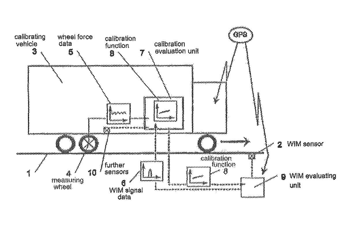
[0015]FIG. 1 shows a road 1 with a WIM sensor 2 (Weigh in Motion) built therein, said WIM sensor being connected to a WIM evaluating unit 9. A calibrating vehicle 3 is represented on road 1, here in the form of a lorry. The arrow direction indicates the driving direction of calibrating vehicle 3.

[0016]WIM sensor 2 in each case measures dynamic signal S of a vehicle 3 as it passes over, and this measurement is schematically represented in FIG. 1 as time-dependent WIM signal data 6. After the measurement, said data are relayed to WIM evaluating unit 9 and are amplified there if need be, evaluated and / or processed in another form.

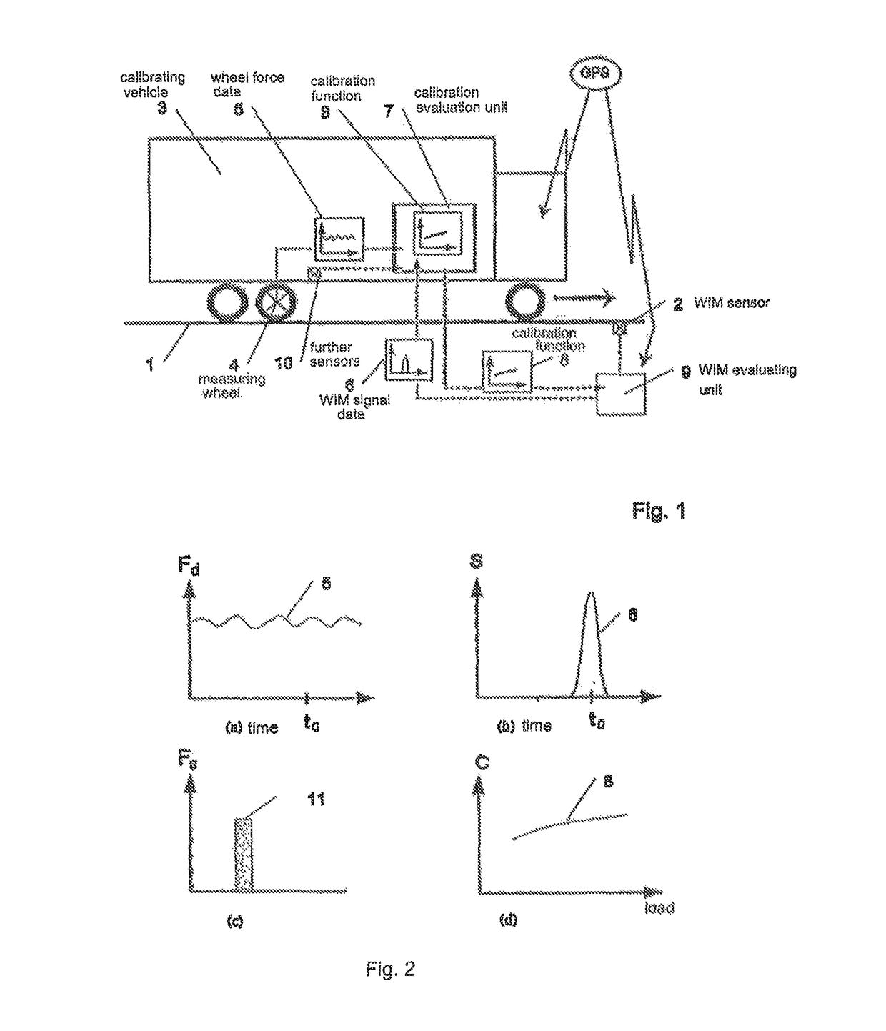
[0017]At least one of the wheels of calibrating vehicle 3 is fitted with a measuring wheel 4, which permits the dynamic wheel force, which is acting in each case on the road or on the WIM sensor, to be ascertained during travel. These wheel force data 5 can be measured time- or location-dependent. These data 5 can also be amplified, evaluated and / or processed ...


PUM


Abstract

A method for calibrating a WIM (Weigh in Motion) sensor built into a road during travel of a calibrating vehicle measures the dynamic wheel force on the road and on the WIM sensor directly at the measuring wheel, depending on time or location. These wheel force data are transmitted to an evaluating unit. As the calibrating vehicle passes over, WIM signal data are simultaneously measured at the WIM sensor and transmitted to the evaluating unit. The wheel force data are synchronized with the WIM signal data in the evaluating unit. A calibration function is determined by comparing the dynamic wheel force data with the WIM signal data.

Description

CROSS-REFERENCE TO RELATED APPLICATIONS[0001]This application claims priority to International Application Serial No. PCT / CH2011 / 000060 filed Mar. 24, 2011, which claims priority to Swiss Application No. CH 486 / 10 filed Apr. 1, 2010. International Application Serial No. PCT / CH2011 / 000060 is hereby incorporated herein for all purposes by this reference.FIELD OF THE INVENTION[0002]The invention relates to a method for calibrating a WIM (Weigh-in-Motion) sensor built into a road, the sensor being suitable for determining the dynamic and / or static weight of a vehicle as it is passing over the WIM-sensor.BACKGROUND[0003]Typical WIM systems comprise two induction loops for the classification of vehicles as well as two series of WIM-sensors, which are built into a road spaced apart approx. 4 m from one another. The WIM-sensors detect signals on the basis of the loads that are transferred from the vehicle via the individual wheels in each case to the road or to the sensor. With the aid of a...

Claims


Application Information

Patent Timeline
Patent Type & Authority Patents(United States)
IPC IPC(8): G01G19/02G01G23/01
CPCG01G23/01G01G19/022G01G19/02
Inventor HOFMANN, ADRIANCORNU, DAVIDCALDERARA, RETO
Owner KISTLER HLDG AG
Why Eureka
Try Eureka