
Charge amount display apparatus of an electric vehicle including a charge limit value

a technology of charge limit value and display apparatus, which is applied in the direction of electric devices, battery/fuel cell control arrangement, instruments, etc., can solve the problems of driver forgetting to set the limit value, driver may not be aware of the limit value setting,

Active Publication Date: 2017-12-26
MITSUBISHI MOTORS CORP
View PDF6 Cites 3 Cited by
  • Summary
  • Abstract
  • Description
  • Claims
  • Application Information

AI Technical Summary

Benefits of technology

This patent is about a device that helps drivers know they are charged less than full capacity when using an electric vehicle.

Problems solved by technology

If a person other than a driver sets the limit value, however, the driver may fail to be aware that the limit value has been set.
Moreover, if the driver sets the limit value a while ago, for example, there is a possibility that the driver forgets setting the limit value.

Method used


Image

  • Charge amount display apparatus of an electric vehicle including a charge limit value
  • Charge amount display apparatus of an electric vehicle including a charge limit value
  • Charge amount display apparatus of an electric vehicle including a charge limit value

Examples


embodiment 1

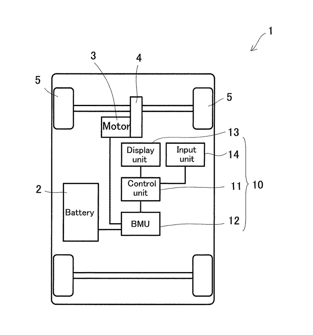
[0016]FIG. 1 is a schematic view showing the configuration of a charge amount display apparatus of an electric vehicle according to the present embodiment. An electric vehicle 1 is equipped with a battery 2, which is a secondary or rechargeable battery, and a motor 3 actuated by the supply of electric power from the battery 2. The battery 2 can be charged by an external power supply (not shown). The motor 3 is coupled to driving wheels (in the present embodiment, front wheels) 5 via a drive mechanism 4. The motor 3 drives the driving wheels 5 via the drive mechanism 4 and, during a so-called regenerative operation, generates electricity upon rotations of the driving wheels 5, and supplies the resulting electric power to the battery 2. A control unit 11 to be described later controls, as appropriate, power supply from the battery to the motor

[0017]A charge amount display apparatus 10 loaded on the electric vehicle 1 is equipped with the control unit 11, a BMU 12 as an example of a ch...

embodiment 2

[0060]The charge amount display apparatus 10 according to Embodiment 1, as shown in FIGS. 3A to 3C, sets the charge limit value by selecting the number of the segments, but such an embodiment is not limitative.

[0061]FIG. 5 is a view showing an example of the display unit in setting the charge limit value. The same constituents as those in Embodiment 1 are assigned the same numerals as in Embodiment 1, and duplicate explanations are omitted.

[0062]A setting screen for a charge amount is displayed in the second display region 22. A frame line 33 of such a size as to be capable of accommodating all the segments 31 is displayed in the center of the second display region 22.

[0063]Three options, described as “Decrease”, “Increase”, and “Decide”, are displayed below the frame line 33. Any of these options can be chosen by operating the input unit 14.

[0064]When the option “Increase” is chosen by the input unit 14, the control unit 11 increases the number of the segments 31, which are to be d...


PUM


Abstract

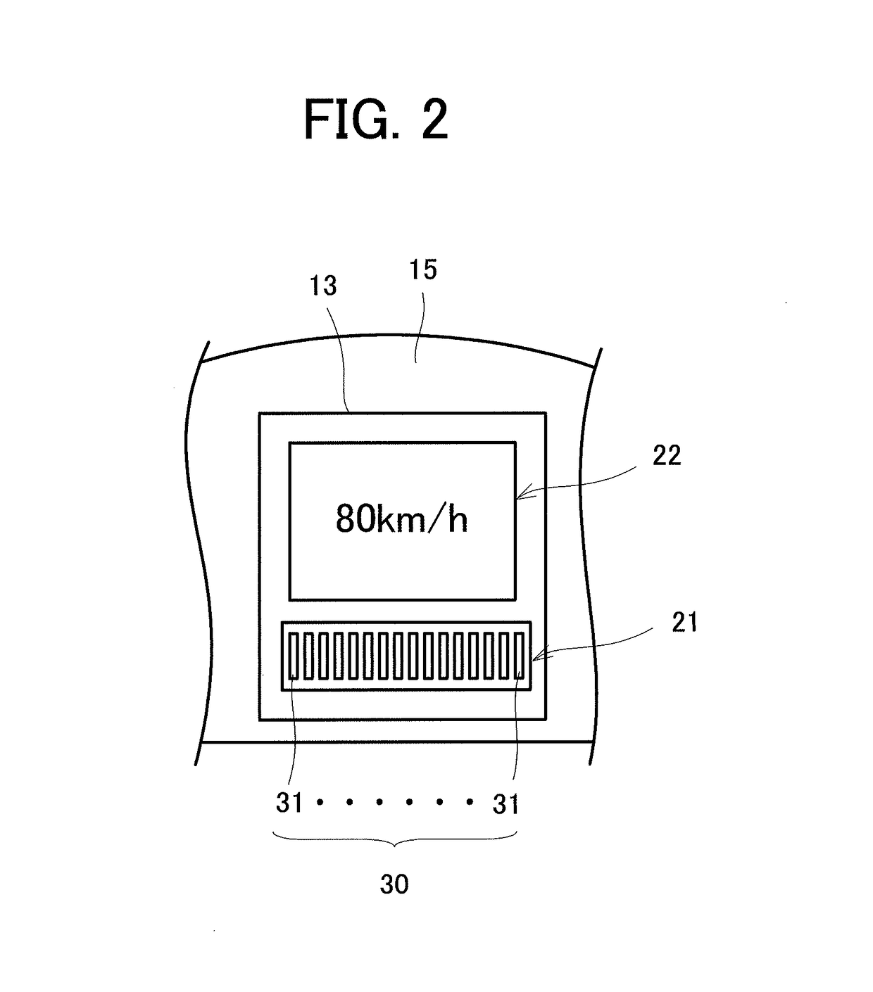
A charge amount display apparatus of an electric vehicle, which enables a driver to be easily aware that a charge amount has been set at a value less than a full charge, is provided. The charge amount display apparatus comprises a control unit 11 for setting a charge limit value which serves as the upper limit of the charge amount of a battery 2; and a display unit 13 for displaying a maximum charge amount, to which the battery 2 can be charged, and the charge limit value. The maximum charge amount is displayed by a segment group 30 composed of a plurality of segments 31 arranged side by side in one direction for representing the charge amount of the battery 2. The segments 31a for a value equal to or lower than the charge limit value, and the segments 31b for a value higher than the charge limit value are displayed in different colors. The segments for a charge amount equal to or lower than the charge limit value are displayed in a first region 21a of a first display region 21 of the display unit 13. A mark 32 indicating that the charge limit value has been set is displayed between the first region 21a and a second region 21b.

Description

[0001]The entire disclosure of Japanese Patent Application No. 2014-263343 filed on Dec. 25, 2014 is expressly incorporated by reference herein.TECHNICAL FIELD[0002]This invention relates to a charge amount display apparatus of an electric vehicle, the apparatus making it easy for a driver to recognize the set charge amount of a battery in an electric vehicle in which the charge amount of the battery can be set arbitrarily as a countermeasure against regenerative braking insufficiency during a full charge.BACKGROUND ART[0003]In recent years, electric vehicles equipped with a motor to be driven by a rechargeable battery have come into widespread use. Among such electric vehicles is one which recharges the battery using electric power generated by a regenerative brake for efficient use of energy accumulated in the battery.[0004]During travel on a downward slope immediately after full charging of the battery, for example, charging by regenerative braking results in a full charge withou...

Claims


Application Information

Patent Timeline
Patent Type & Authority Patents(United States)
IPC IPC(8): G08B21/00B60L11/18B60L3/00H02J7/00B60C9/00
CPCH02J7/0047B60C9/00B60L3/0046B60L11/1861Y02T10/7044H02J2007/005Y02T10/705Y02T10/7005B60L2250/16B60L58/12B60K35/00B60K35/10B60K35/22B60K35/29B60K2360/186B60K35/81B60L58/13Y02T10/70H02J7/0048B60Q9/00
Inventor HATSUMI, NORIHIKOMORO, KOSUKEFUJIKAWA, YOSHIHIDETANO, KOICHI
Owner MITSUBISHI MOTORS CORP
Learn More