
Smoke filter

a filter and smoke technology, applied in the field of smoke filters, can solve the problems of polluting the operating environment, endangering the health of the operator, and filtration cloth, and achieve the effects of increasing the filtration area of the filtration cloth, reducing pollution, and reducing the risk of contamination

Inactive Publication Date: 2018-01-02
CHENG CHIEH YUAN
View PDF14 Cites 0 Cited by
  • Summary
  • Abstract
  • Description
  • Claims
  • Application Information

AI Technical Summary

Benefits of technology

The invention is a smoke filter designed to effectively remove smoke and ash produced by electric welding. It features a large filtration area and is easy to replace and maintain. The filter uses a blower to suck in the smoke and ash, which is then filtered out by a filtration cloth. The filter's unique design increases the filtration area and efficiency. The control device automatically keeps the filter in good condition and the paper conveying and winding seats can be easily detached and replaced. Overall, the invention has the advantages of a larger filtration area, higher efficiency, and a simplified structure that is easy to maintenance and replace.

Problems solved by technology

The smoke produced by electric welding frequently contains heavy metal volatile matter, and when an operator is exposed in a working environment full of electric welding smoke, the operator will be unavoidable to inhale too much heavy metal contained in the electric welding smoke, thus not only polluting an environment of operation but endangering the operator's health as well.
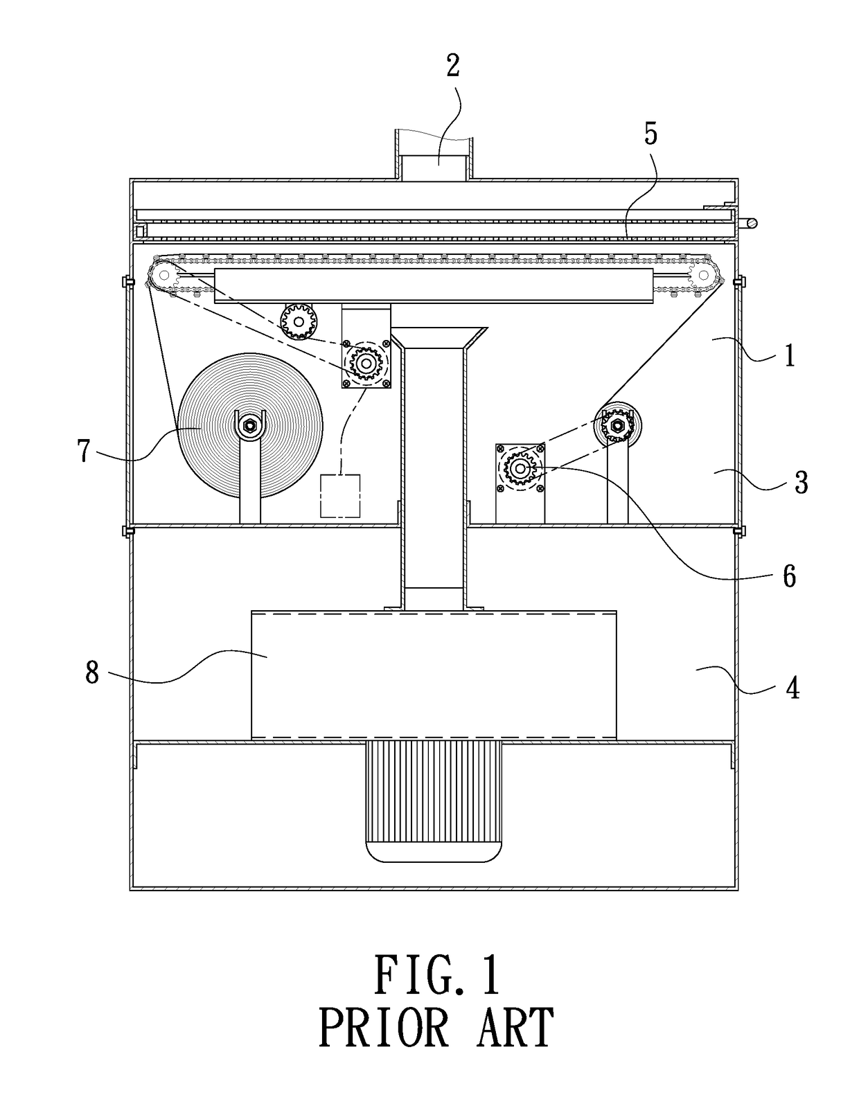
1. Since the interior members of the movable filtration device 6 is various and numerous; therefore, the filtration cloth 7 is hard to be replaced and easy to be damaged, and the movable filtration cloth device 6 has its interior members respectively distributed and provided in the housing 1, as shown in FIG. 1; therefore, when the movable filtration cloth device 6 is damaged, it is difficult in maintenance.
2. The filtration cloth 7 in the movable filtration cloth device 6 is received in the interior of the housing 1 and the movable filtration cloth device 6 has the filtration cloth 7 positioned horizontally for carrying out filtration; therefore, the filtration area of the filtration cloth 7 is too small and hence filtration is not sufficiently effective.

Method used


Image

  • Smoke filter
  • Smoke filter
  • Smoke filter

Examples


Embodiment Construction

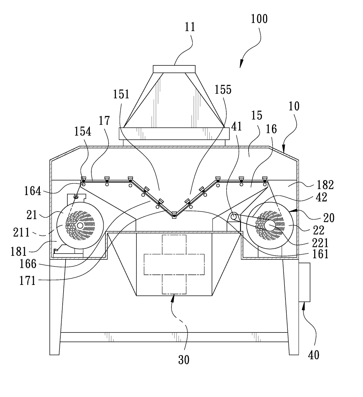
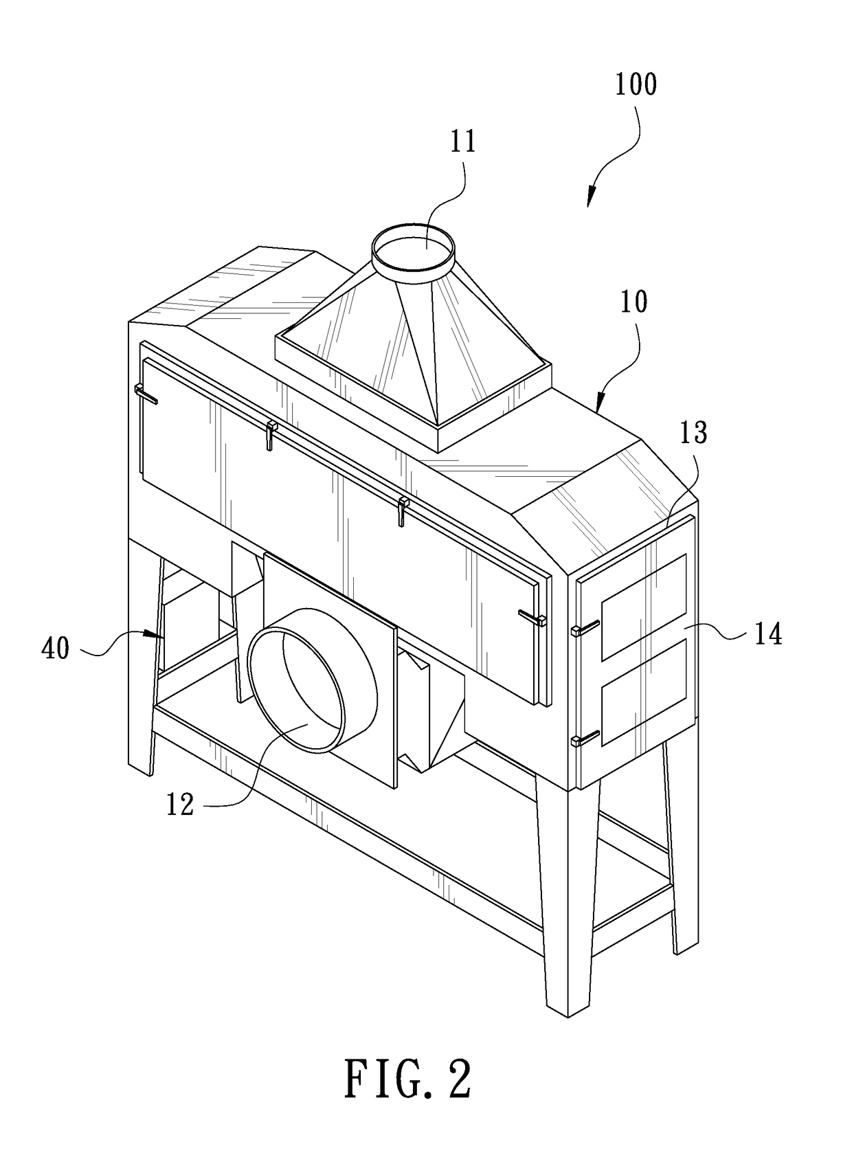
[0020]A preferred embodiment of a smoke filter 100 in the present invention, as shown in FIGS. 2 and 3, includes a housing 10, a replaceable filtration cloth device 20, a blower 30 and a control device 40 as main components combined together.

[0021]The housing 10 consists of an upper casing 15 and a lower casing 16 combined together. The upper casing 15 has its interior formed with an upper accommodating chamber 153 and its topside longitudinally provided with an air intake 11, and the top portion of the housing 10, adjacent to the air intake 11, is gradually expanded downward. The upper casing 15 further has its bottom side longitudinally bored with a first opening 155, and the upper accommodating chamber 153 of the upper casing 15 is by degree expanded from the air intake 11 toward the first opening 155. The lower casing 16 has its interior formed with a lower accommodating chamber 163 and its topside longitudinally bored with a second opening 166 corresponding with the first openi...


PUM

PropertyMeasurementUnit
filtration areaaaaaaaaaaa
areaaaaaaaaaaa
sizeaaaaaaaaaa

Abstract

A smoke filter includes a housing formed with an upper casing and a lower casing. A filtration passage with a bending section is formed between the upper casing and the lower casing and further, a replaceable filtration cloth device is provided in the interior of the housing and the filtration cloth of the replaceable filtration device passes through the filtration passage. By so designing, the smoke filter of this invention is able to increase a filtration area, enhance filtration efficiency and diminish the size of the housing and further, the smoke filter of this invention is simple in structure and convenient in maintenance and in replacement of the filtration cloth.

Description

BACKGROUND OF THE INVENTION[0001]1. Field of the Invention[0002]This invention relates to a smoke filter, particularly to one that is able to effectively dispose of the smoke and the ashes produced by electric welding.[0003]2. Description of the Prior Art[0004]A commonly seen metal welding plant of argon welding, electric welding and heat treatment is easy to produce a large quantity of smoke during electric welding processing. The smoke produced by electric welding frequently contains heavy metal volatile matter, and when an operator is exposed in a working environment full of electric welding smoke, the operator will be unavoidable to inhale too much heavy metal contained in the electric welding smoke, thus not only polluting an environment of operation but endangering the operator's health as well. Therefore, an air filter specially used for electric welding is developed used. The conventional air filter, referring to FIG. 1, includes a housing 1 having one top end bored with a t...

Claims


Application Information

Patent Timeline
Patent Type & Authority Patents(United States)
IPC IPC(8): B01D46/00B01D46/44B01D46/18B01D39/08
CPCB01D46/18B01D39/08B01D46/44B01D46/185B01D2239/06
Inventor CHENG, CHIEH-YUAN
Owner CHENG CHIEH YUAN
Learn More