Corrugated furring strips and use of same in upright wall structures

a technology of corrugated furring and upright wall structure, which is applied in the direction of walls, constructions, covering/linings, etc., can solve the problems of reducing the effectiveness of the insulation layer, material and time-consuming construction methods,

Active Publication Date: 2018-01-02
UKRAINETZ MICHAEL WAYNE
View PDF12 Cites 11 Cited by
  • Summary
  • Abstract
  • Description
  • Claims
  • Application Information

AI Technical Summary

Problems solved by technology

This construction method is material and time intensive, requiring installation of the sheathing, addition of the Z-channels thereto, insertion of the insulation between the Z-channels, subsequent mounting of the hat-channels, and finally installation of the exterior cladding.
In addition, each Z-channel creates a thermal bridge across the insulation layer over the full length of the channel, thereby reducing the effectiveness of the insulation layer.

Method used


Image

  • Corrugated furring strips and use of same in upright wall structures
  • Corrugated furring strips and use of same in upright wall structures
  • Corrugated furring strips and use of same in upright wall structures

Examples


Embodiment Construction

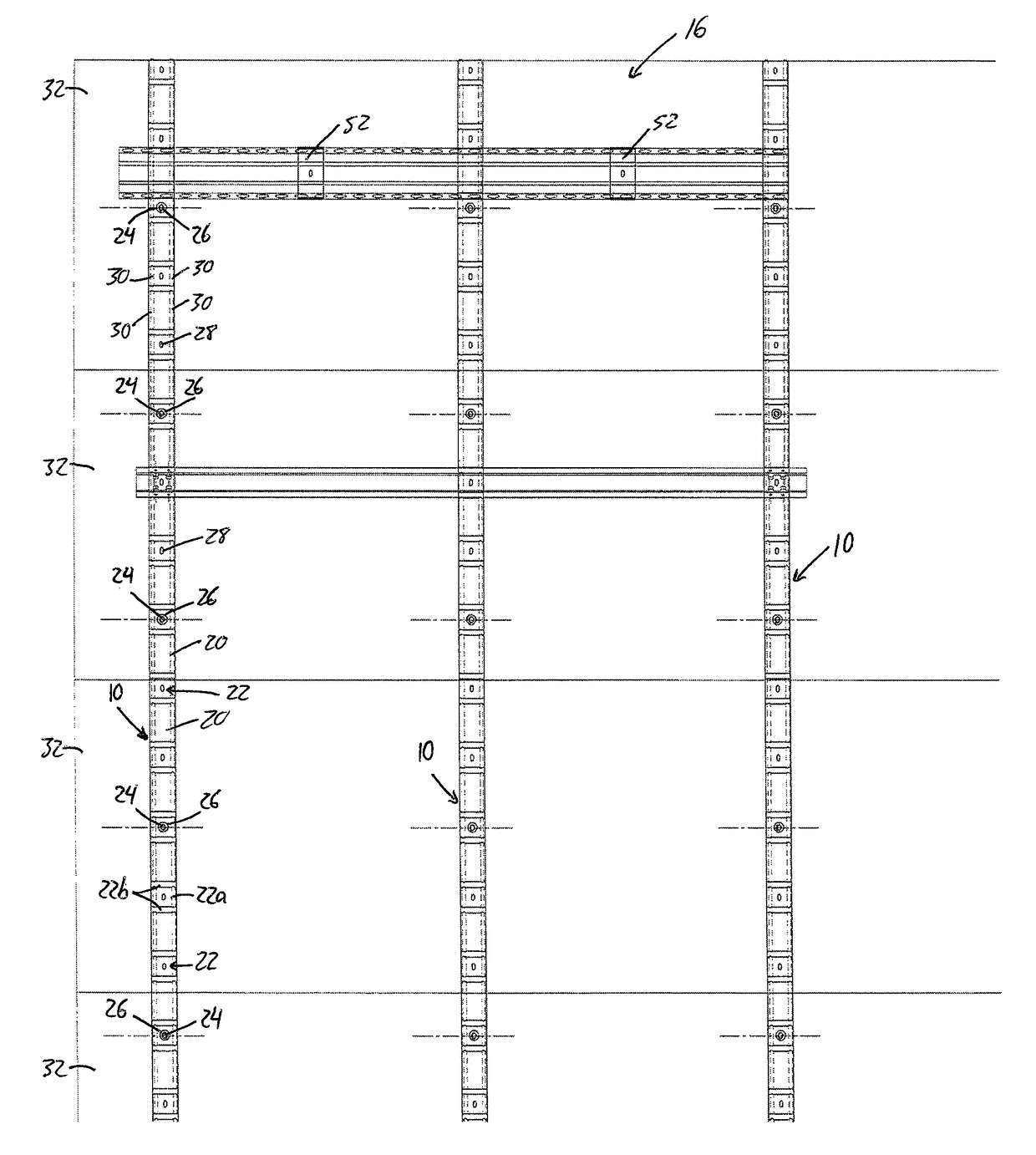
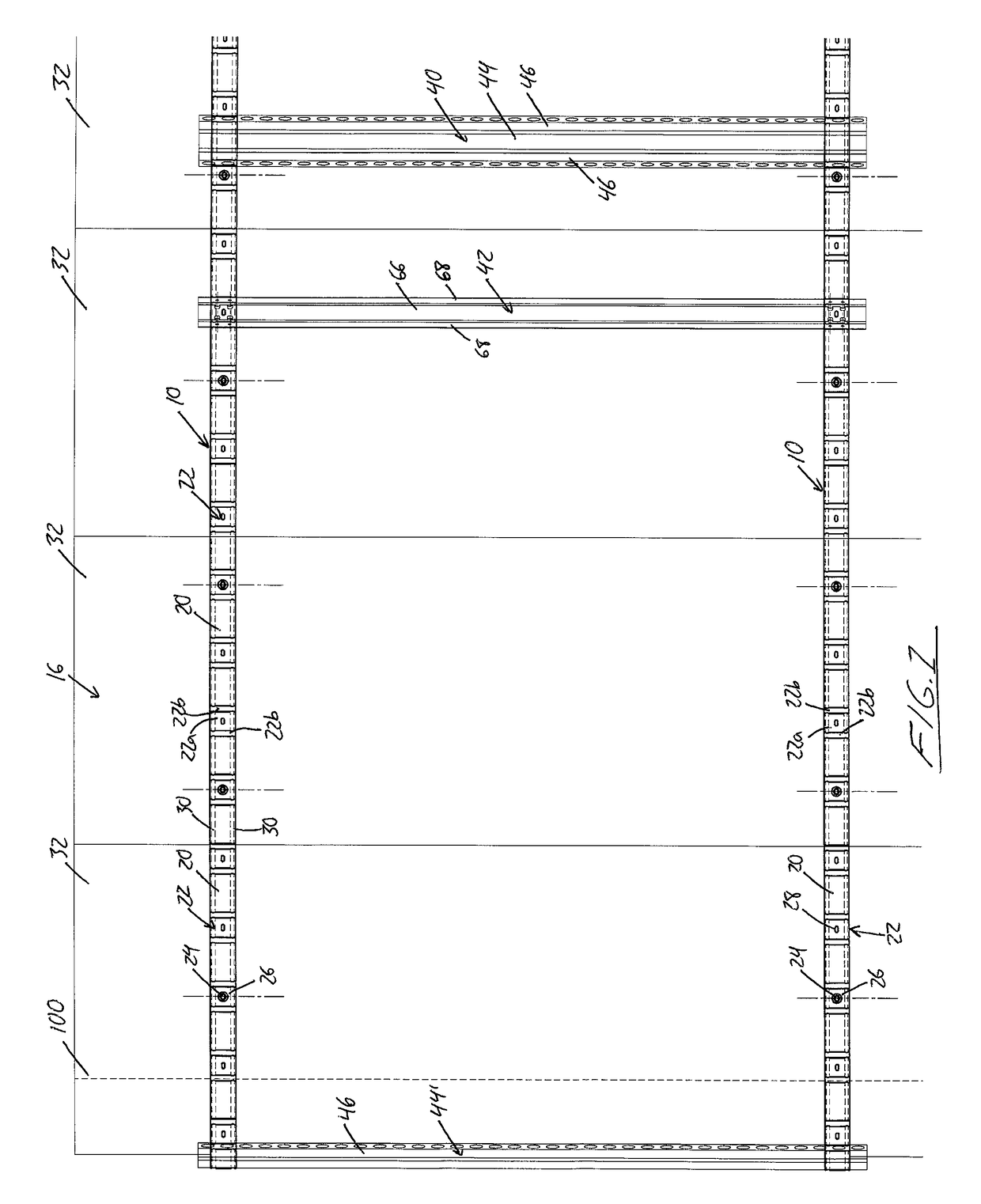
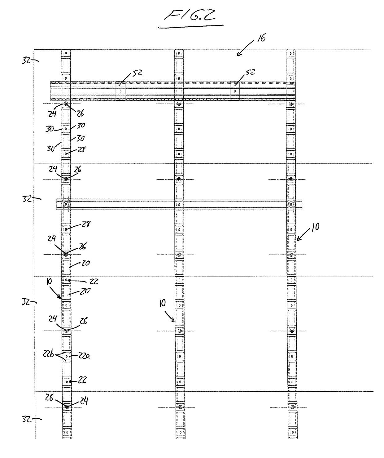
[0041]FIGS. 3A and 3B illustrate a construction of a steel framed externally insulated exterior wall using corrugated metal furring strips 10 to support the final exterior cladding layer 18 of the finished wall. The wall features a series of vertically upright steel studs 12 horizontally spaced apart from one another at regular intervals to form a structural framework of the wall, and a layer of exterior sheathing 14 fastened to the studs 12 at outwardly facing edges thereof. A layer of insulation 16 resides opposite the studs on the external side of the sheathing 14, and may feature semi-rigid mineral wool, rigid insulation, insulation panels, structural insulated panels (SIP), or other thermal insulation. Each furring strip 10 is mounted opposite the sheathing 14 on the outer side of the insulation layer 16, and is fastened to the studs 12 through the insulation layer 16 and underlying sheathing 14. The finished wall is completed by the installation of cladding 18 over the furring...


PUM


Abstract

Corrugated furring strips are used on the outer side of an exterior insulation layer in an exterior wall construction. The corrugated furring strips support a final cladding layer at an offstanding position from the insulation, thereby providing a rainscreen. The corrugated furring strips are fastened to the framework of the wall through the exterior insulation layer. Optional bridging members shaped to conformingly mate with lands and grooves of the corrugated furring straps cooperate therewith to define a support grid with improved load capacity for heavier cladding materials and more fastening location options. The insulation layer is free of any thermal bridges other than the insulation-penetrating fasteners used to support the furring and optional bridges. Thermally insulative washers isolate the furring and optional bridges from the fasteners to further improve the insulating effect of the wall.

Description

CROSS REFERENCE TO RELATED APPLICATIONS[0001]This application claims benefit under 35 U.S.C. 119(a) of Canadian Patent Application No. 2,907,245, filed Oct. 5, 2015, the entirety of which is incorporated herein by reference.FIELD OF THE INVENTION[0002]The present invention relates generally to building construction, and more particularly to the use of corrugated furring strips that are particularly useful in steel-framed cladded wall construction with a rainscreen, where potential benefits include reduced thermal bridging and improved ease of installation.BACKGROUND[0003]In commercial grade building construction, it is common to employ a multi-layered wall construction in which vertical steel studs are covered with an external sheathing layer, over which a series of metal Z-channels are installed with rigid insulation panels between them to define an external insulation layer, over which another series of metal channels (e.g. hat-channels) are then installed as furring to support th...

Claims


Application Information

Patent Timeline
Patent Type & Authority Patents(United States)
IPC IPC(8): E04B2/60E04C3/00E04B1/41E04B1/70E04B2/56
CPCE04B2/60E04B1/40E04C3/00E04B1/7076E04B2/56E04B1/7038E04F13/0803E04F13/12E04F19/06E04B1/388
Inventor UKRAINETZ, MICHAEL WAYNE
Owner UKRAINETZ MICHAEL WAYNE
Why Eureka
Try Eureka