
Stereographic image detail uniformity of a panoramic video capture device having an optical gradient

Inactive Publication Date: 2018-01-02
HOYOS INTEGRITY CORP
View PDF2 Cites 1 Cited by
  • Summary
  • Abstract
  • Description
  • Claims
  • Application Information

AI Technical Summary

Benefits of technology

The present invention describes a method and system for improving the quality of media from a panoramic video capture device. This is achieved by using a fixed smoothing function to reduce differences in image detail of a stereographic image. The system includes a set of lenses and an image sensor, which can capture a wide-angled image. The image sensor can analyze the image to determine a pixel degradation curve, which reflects the quality of the image. The system then applies a smoothing function to the image to reduce variations in image detail. The technical effect of this invention is to produce high-quality media from panoramic cameras, even without the need for costly and time-consuming post-processing.

Problems solved by technology

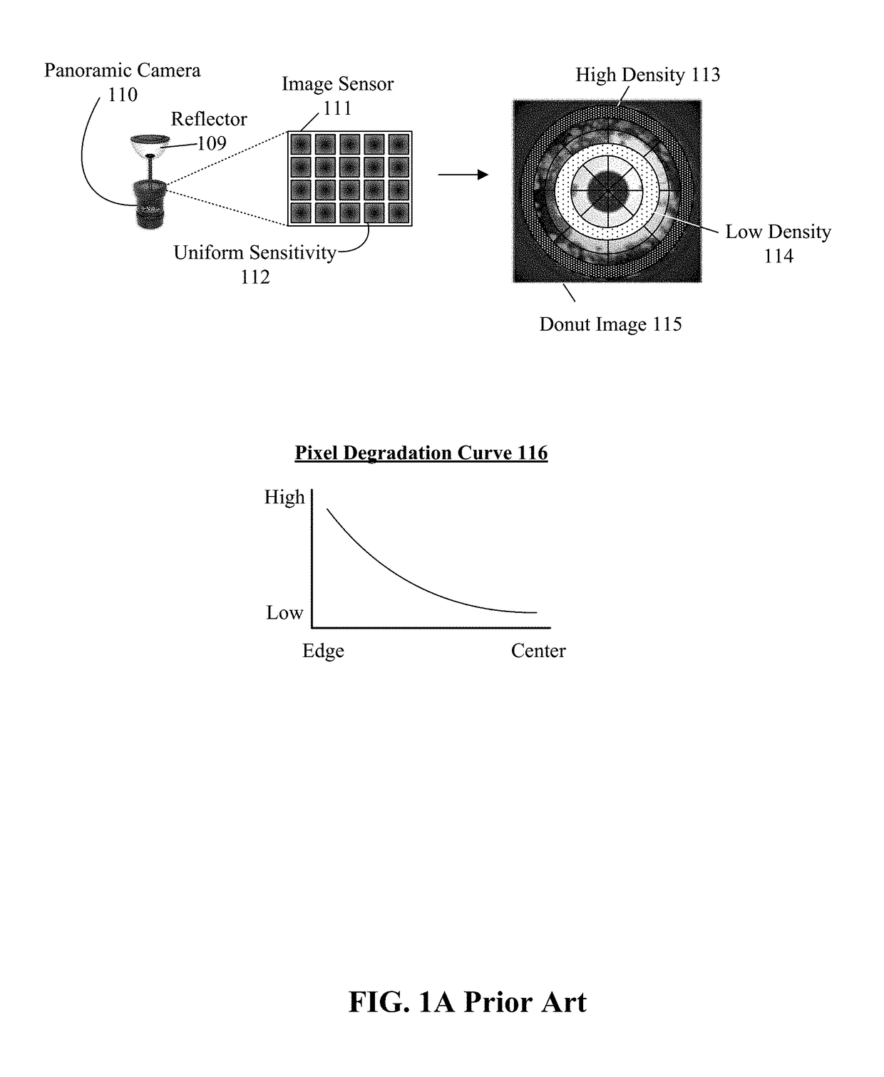
One property of the projection is often non-uniform distribution of image detail per sensor capture region, which results from environmental light being distorted before being directed an image capture sensor.
In other words, an intensity of the light (or an amount of image detail contained within a squared unit of light) striking the image capture sensor is non-uniform.
When an intensity of light is altered prior to being directed to the image sensor 111, however, problems may occur.
Of course, some loss always occurs when converting an optical image (which is analog) to an electronic signal (which digitally represents data of the analog image).
This problem resulting from annular optical distortions as detailed herein is not known to be widely recognized outside this disclosure, nor are the solutions presented herein known to exist in known prior art.

Method used


Image

  • Stereographic image detail uniformity of a panoramic video capture device having an optical gradient
  • Stereographic image detail uniformity of a panoramic video capture device having an optical gradient
  • Stereographic image detail uniformity of a panoramic video capture device having an optical gradient

Examples


embodiment 130

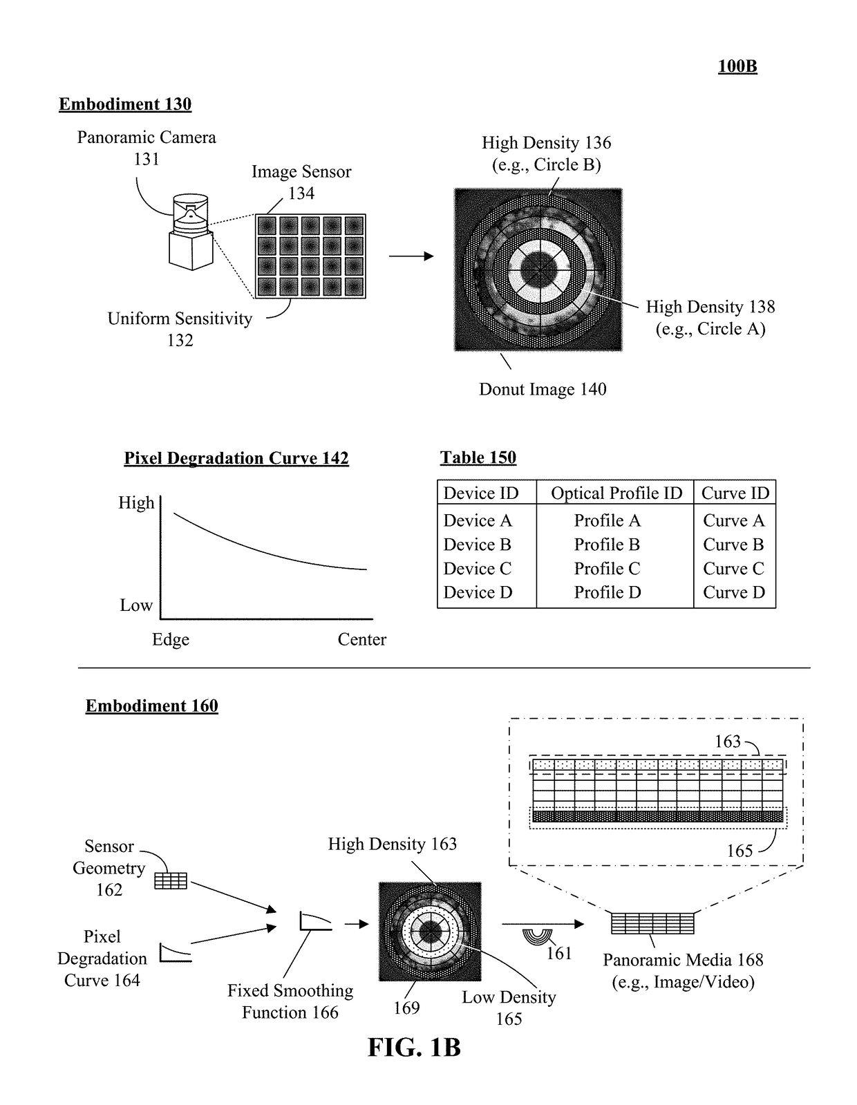
[0040]In embodiment 130, image sensor 134 can be designed for uniform sensor sensitivity. That is, each subarea of the image sensor has the same relative sensitivity for converting light into electronic data as every other subarea of the image sensor 134. This uniform sensor sensitivity results in a production of a donut image 140 having a uniform pixel density. For instance, the photosensor array of the image sensor 134 can conform to a grid with an equal distribution of photosensors. The panoramic camera 131, however, has an annular optical gradient, which results in non-uniform image information loss when the image sensor 134 performs the A / D conversion. This is because the density of image information has been optically biased by the quadric reflector so that some regions of image filled data being captured by the image sensor 134 contain more optical information about the object in the first reference plane than others, yet the sensitivity of the image sensor 134 is uniform. Vi...

embodiment 160

[0043]Once the pixel degradation curve 142 for a given panoramic camera 131 and the image sensor geometry are known, a fixed smoothing function is able to be defined. The fixed smoothing function is applied when converting the donut image 140 of reference plane two into the flat image of reference plane three. To elaborate as illustrated by embodiment 160, a sensor geometry 162 and a pixel degradation curve 164 parameters can be utilized to create a fixed smoothing function for an image sensor (e.g., sensor 134) of a panoramic camera (e.g., 131). The fixed smoothing function can be determined manually, semi-automatically, or automatically. In one embodiment, the fixed smoothing function 166 can be employed to enhance a panoramic media 168. In the embodiment, the smoothing function 166 can be an additive smoothing function which can increase the pixel density of regions of media 168. For example, the function 166 can include Laplace smoothing technique. The smoothing function can be ...

embodiment 170

[0053]In embodiment 170, a panoramic camera 171 can have an image sensor 174. Image sensor 174 can have proprietary characteristics which can include non-uniform pixel density 161. That is, the photosensor array of the image sensor 174 can conform to a grid with an equal distribution of photosensors. The sensor 174 can produce an image 179 with non-uniform information density per area. That is, image 179 can have a high information density at the edges and towards the center of the image. In one instance, a more uniform pixel density of the donut image can be achieved by permitting the sensor 174 of the camera 171 to capture greater quantities of environmental light to regions of an image sensor which would traditionally be associated with low pixel density. Thus, light intensity is adjusted to compensate for the annular optical gradient.

[0054]It should be appreciated that a range of tolerances can be associated with the device (e.g., calibration, configuration settings) to enable s...


PUM


Abstract

A stereographic image associated with a panoramic camera can be identified. The panoramic camera can include of a set of lenses and an image sensor. A pixel degradation curve associated with the image and / or the hardware of the panoramic camera can be determined, as can a sensor geometry of an image sensor used by the panoramic camera. A fixed smoothing function based on the pixel degradation curve and / or the sensor geometry can be created. The fixed smoothing function can be applied to a stereographic image to modify the image so it includes substantially uniform image detail per image region.

Description

BACKGROUND[0001]The present invention relates to the field of panoramic media capture and, more particularly, to improving stereographic image detail uniformity of a panoramic video capture device having an annular optical gradient.[0002]Panoramic cameras often utilize traditional image sensors to capture a 360 degree view of a real world environment. These image sensors produce a stereographic projection of the real world view as an image. For example, images captured with a 360 degree camera appear as a “little world” doughnut image (e.g., circular image). The characteristics of the projection include resolution, image size, and the like. One property of the projection is often non-uniform distribution of image detail per sensor capture region, which results from environmental light being distorted before being directed an image capture sensor. In other words, an intensity of the light (or an amount of image detail contained within a squared unit of light) striking the image captu...

Claims


Application Information

Patent Timeline
IPC IPC(8): H04N5/232G06T5/00H04N13/00
CPCH04N5/23238H04N13/0055G06T5/002H04N13/0029H04N13/0018G06T2207/10012G06T2207/20224G06T2207/20182G06T3/4038H04N23/55H04N23/698H04N25/61G06T5/70H04N13/139H04N13/189
Inventor DE LA CRUZ, MOISESSHEMELYNCE, JOHNNGUYEN, HAOPATEL, BIRENLEIZEROVICH, GUSTAVO D.VERMA, AMIT
Owner HOYOS INTEGRITY CORP
Learn More