Solder supply system

a supply system and soldering technology, applied in the direction of metal working equipment, manufacturing tools, soldering apparatus, etc., can solve the problems of improper verification work of solder containers, inability to prevent mistakes, and inability to perform solder verification work

Active Publication Date: 2018-01-02
FUJI CORP
View PDF7 Cites 0 Cited by
  • Summary
  • Abstract
  • Description
  • Claims
  • Application Information

AI Technical Summary

Benefits of technology

[0010]According to the solder supply system disclosed in claim 1, it is judged whether the solder container is set in the solder supply device. Also, in a case in which it is judged that the solder container is not set in the solder supply device, for example, reading of an identification code such as a barcode by a reading device such as a barcode reader is restricted. That is, before a solder container is set the solder supply device, reading of the identification code by the reading device is restricted. Thus, verification work is only able to be performed for solder containers actually set on the solder supply device, which prevents operator mistakes and enables verification work of solder containers to be performed appropriately.
[0012]Further, according to the solder supply system disclosed in claim 3, the solder container is housed inside an outer tube along with a nozzle and a piston. At least a portion of the outer tube is transparent, such that the barcode affixed to the solder container housed inside the outer tube is viewable from outside the outer tube. Thus, it is possible to read the barcode from outside the tube using the barcode reader, which allows verification work of a solder container set in the solder supply device to be performed appropriately.

Problems solved by technology

However, there are cases in which operator mistakes are not prevented, such that solder verification work is not performed appropriately.
In this case, verification work of the solder container is not performed appropriately.

Method used


Image

  • Solder supply system
  • Solder supply system
  • Solder supply system

Examples


Embodiment Construction

[0020]The following describes in detail referring to the figures an example embodiment of the present disclosure.

[0021]Configuration of Solder Printer

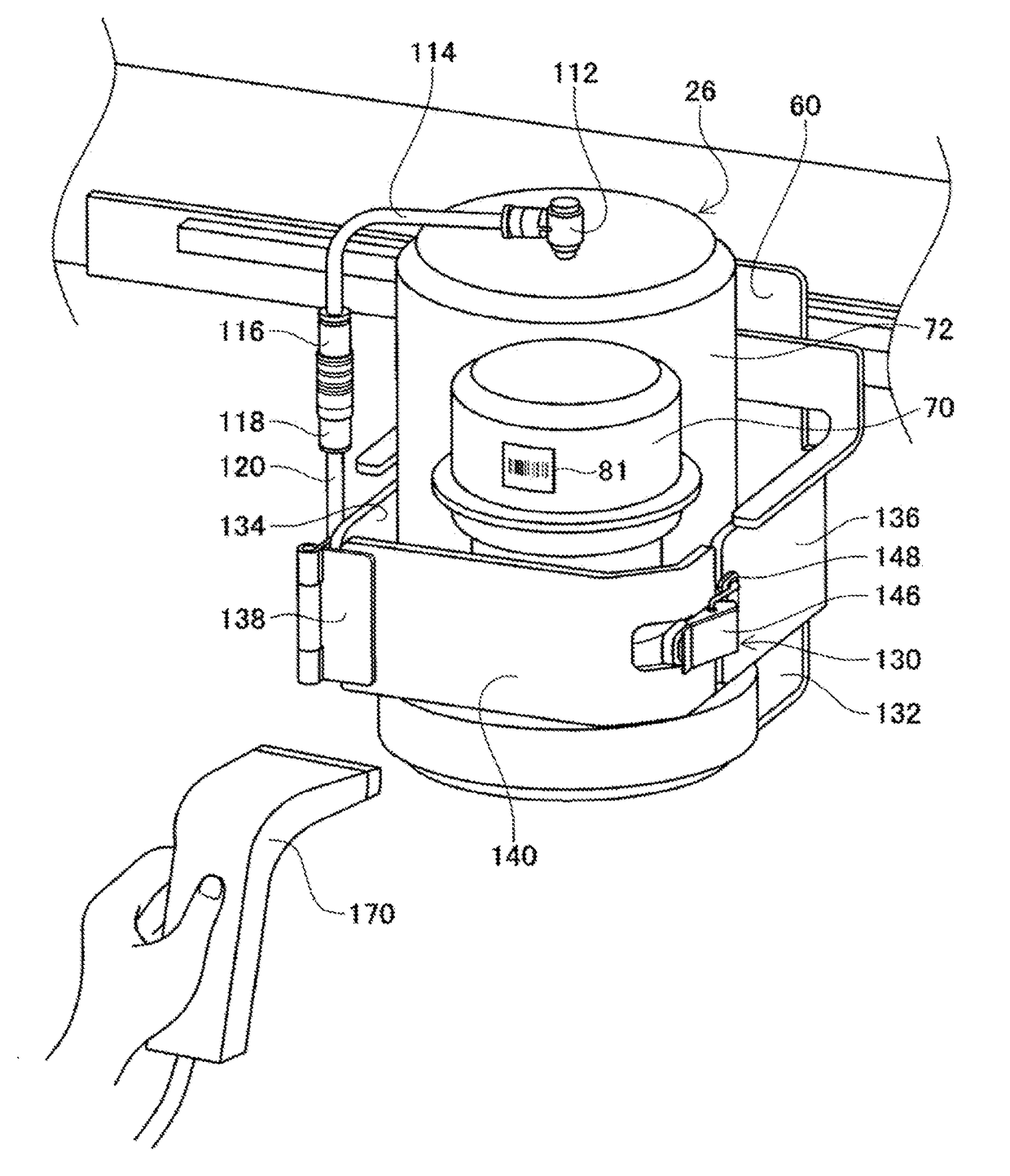
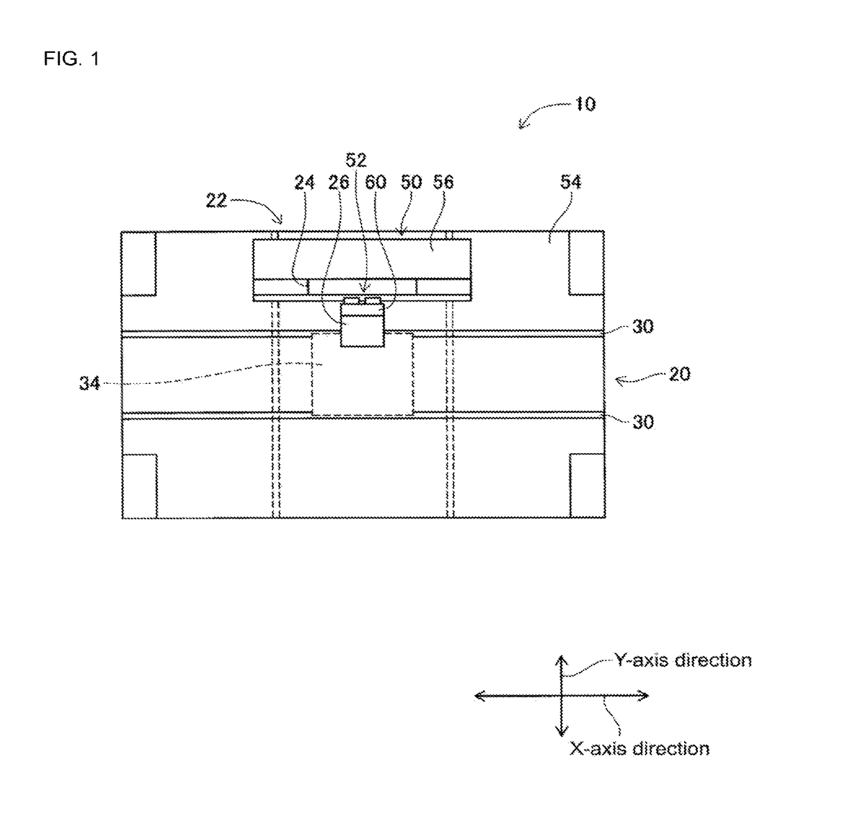
[0022]FIG. 1 shows solder printer 10 as an embodiment of the disclosure. Solder printer 10 is a device that prints solder paste onto a circuit board. Solder printer 10 is provided with conveyance device 20, moving device 22, squeegee device 24, and solder supply device 26.

[0023]Conveyance device 20 has a pair of conveyor belts 30 that extend in the X-axis direction, and electromagnetic motor (refer to FIG. 4) 32 that moves conveyor belts 30. The pair of conveyor belts 30 support circuit board 34 and circuit board 34 is conveyed in the X-axis direction by the driving of electromagnetic motor 32. Also, conveyance device 20 has holding device (refer to FIG. 4) 36. Holding device 36 fixedly holds circuit board 34 supported by conveyor belts 30 in a predetermined position (the position at which circuit board 34 is shown in FIG. 1). Note tha...


PUM

PropertyMeasurementUnit
transparentaaaaaaaaaa
pressureaaaaaaaaaa
diameteraaaaaaaaaa

Abstract

A solder supply system that judges whether a solder cup is set on a solder supply device. In a case in which it is judged that the solder cup is set on the solder supply device, reading a barcode by a barcode reader is allowed. In contrast, in a case in which it is judged that the solder cup is not set on the solder supply device, reading a barcode by the barcode reader is restricted. That is, reading a barcode by the barcode reader before the solder cup is set inside an outer tube is restricted, while reading a barcode by the barcode reader is allowed when the solder container is set inside the outer tube.

Description

TECHNICAL FIELD[0001]The present disclosure relates to a solder supply system provided with a solder supply device for supplying solder from a solder container housing liquid solder, the solder container being tubular and open at one end.BACKGROUND ART[0002]Among solder supply devices, there is a solder supply device that has a solder container housing liquid solder inside thereof, and a piston engaged inside the solder container, and that supplies solder in the solder container by raising the pressure inside the solder container by moving at least one of the solder container and the piston. With this type of device, when a solder container becomes empty, the empty solder container is exchanged with a new solder container. Here, conventionally verification work is performed of new solder containers. With the solder supply system according to the patent literature below, verification work of solder containers is performed by reading a barcode affixed to the solder container with a ba...

Claims


Application Information

Patent Timeline
Patent Type & Authority Patents(United States)
IPC IPC(8): H05K3/34B23K3/06B23K3/08B23K101/42
CPCH05K3/3478B23K3/0638B23K3/08H05K2203/0126B23K2201/42H05K3/3484B23K2101/42H05K3/3485
Inventor KATO, MITSUAKIFUJITA, YOJI
Owner FUJI CORP
Why Eureka
Try Eureka