Vehicle meter indicator device

a technology of vehicle meter and indicator device, which is applied in the direction of simultaneous indication of multiple variables, instruments, transportation and packaging, etc., can solve the problems of image motion that produces a sense of discomfort, and the occupants are more likely to feel discomfort. , to achieve the effect of reducing the cost, increasing the rotation speed, and increasing the heat generation

Active Publication Date: 2018-01-16
HONDA MOTOR CO LTD
View PDF4 Cites 0 Cited by
  • Summary
  • Abstract
  • Description
  • Claims
  • Application Information

AI Technical Summary

Benefits of technology

[0008]In light of the foregoing, it is an object of the present invention to provide a vehicle meter indicator device that keeps the cost to a minimum without quickening the updating cycle of an on-screen image and shows an image with minimal sense of discomfort perceived by the occupant.
[0011]According to the first feature of the present invention, during a period of decline in the rotation speed of an internal combustion engine in which a sense of discomfort, attributable to the change in on-screen image, is likely to be conspicuously felt, virtual data is generated on the basis of an arbitrary rotation speed between a rotation speed proportional to the image currently shown on the meter unit and the latest rotation speed immediately before updating detected by the rotation speed sensor, causing the meter unit to show the virtual image proportional to the generated virtual data for updating. This ensures minimal sense of discomfort attributable to the change in on-screen image. Further, it is possible to reduce the device cost while at the same time alleviating a sense of discomfort produced by the difference between the actual rotation speed of the internal combustion engine and the rotation speed shown on the meter unit. Further, there is no need to quicken the updating cycle. This makes it possible to reduce the loads of the display data generator and the virtual data generator and to ensure minimal heat generation from the display data generator and the virtual data generator.
[0013]According to the second feature of the present invention, if the transmission of the internal combustion engine is in the neutral position and idling, it is possible to alleviate a sense of discomfort produced by the difference between the actual rotation speed of the internal combustion engine and the rotation speed shown on the meter unit despite the snapping of the accelerator by the vehicle's occupant. It is possible to alleviate a sense of discomfort produced by the difference between the actual rotation speed of the internal combustion engine and the rotation speed shown on the meter unit particularly when the rotation speed of the internal combustion engine declines following warmup by increasing the rotation speed of the internal combustion engine.
[0017]According to the fourth feature of the present invention, if the change in the rotation speed is smaller than a change threshold, the meter unit shows, for updating, an image proportional to the latest rotation speed immediately before updating, effectively ensuring minimal sense of discomfort attributable to the change in displayed screen.
[0019]According to the fifth feature of the present invention, even if the rotation speed starts to increase after having declined once, the meter unit shows, for updating, virtual data until the rotation speed proportional to the virtual image shown on the meter unit is exceeded. This makes the difference between the actual rotation speed of the internal combustion engine and the rotation speed shown on the meter unit less conspicuous. Further, if the detected rotation speed exceeds the rotation speed proportional to the virtual image, and if the change in the detected rotation speed is greater than the change in the rotation speed proportional to the virtual image, display data is generated on the basis of the detected rotation speed, thus making it possible to detect a significant increase in rotation speed quickly. As a result, an increase in heat generation by the internal combustion engine can be detected as soon as possible. This keeps the cost to a minimum while at the same time effectively ensuring minimal thermal impact on the display data generator and the virtual data generator.

Problems solved by technology

Therefore, an occupant of the vehicle feels a sense of discomfort to the image displayed on the meter unit in some cases.
That is, if the frame interval is longer than the acquisition interval, the frame interval cannot cope with the change in rotation speed, thus resulting in an image motion that produces a sense of discomfort.
As a result, the occupant is more likely to feel a sense of discomfort when the on-screen image of the meter unit changes.
However, quickening the updating cycle of the on-screen image leads to heavier calculation load for the on-screen image, thus resulting in higher cost of the computing device for generating images.

Method used


Image

  • Vehicle meter indicator device
  • Vehicle meter indicator device
  • Vehicle meter indicator device

Examples


Embodiment Construction

[0029]A detailed description will be given below of a vehicle meter indicator device according to the present invention by taking, as an example, a preferred embodiment in relation to a saddle type vehicle to which the vehicle meter indicator device is applied, with reference to the accompanying drawings.

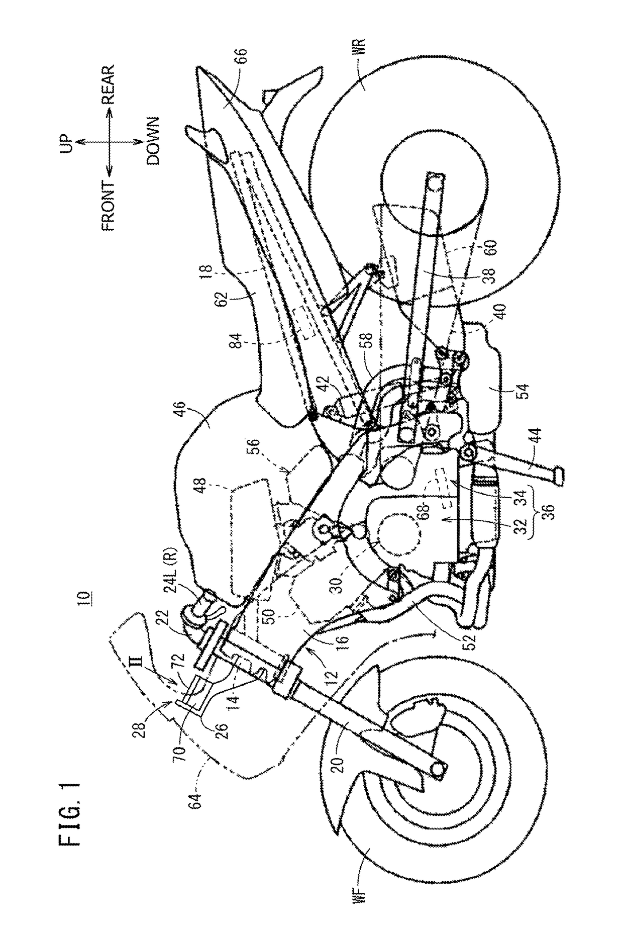
[0030]FIG. 1 is an outer left side view of a motorcycle 10. It should be noted that, unless otherwise specified, the longitudinal, horizontal, and vertical directions of the motorcycle 10 will be described relative to the directions as seen from the driver of the same vehicle 10.

[0031]A vehicle body frame 12 of the motorcycle 10 has a head pipe 14, a main frame 16, and a seat frame 18. The main frame 16 extends rearward and downward from the head pipe 14. The seat frame 18 extends rearward and upward from near the rear portion of the main frame 16. The head pipe 14 pivotally supports a front fork 20 in a rotatable manner. The front fork 20 supports a front wheel WF, i.e., a steering...


PUM


Abstract

To show an image with minimal sense of discomfort felt by an occupant without quickening an updating cycle of an on-screen image, a virtual data generator making up a vehicle meter indicator device generates virtual data based on an arbitrary engine rotation speed between an engine rotation speed proportional to an image currently shown on a liquid crystal display device and a latest engine rotation speed rather than display data based on the latest engine rotation speed immediately before updating if the engine rotation speed declines. This allows the liquid crystal display device to show the generated virtual data on a liquid crystal panel as a virtual image for updating.

Description

BACKGROUND OF THE INVENTION[0001]Field of the Invention[0002]The present invention relates to a vehicle meter indicator device designed to show display data, generated on the basis of the rotation speed of an internal combustion engine, on a meter unit as an image.[0003]Description of Related Art[0004]For example, Japanese Patent No. 5000728 discloses a meter indicator device designed to show, as an image, sensor information from sensors provided on a vehicle. If sensor information is acquired at a longer interval than the frame interval at which an image is to be displayed, the meter indicator device updates the image display position in such a manner that the image moves at the frame interval from a starting point to the image display position calculated on the basis of sensor information acquired at present. The starting point is the image display position calculated on the basis of acquired sensor position.[0005]Incidentally, an image displayed on the meter unit making up the me...

Claims


Application Information

Patent Timeline
Patent Type & Authority Patents(United States)
IPC IPC(8): G01M15/04G01D1/00G01D3/10G01D7/06
CPCG01M15/046G01D1/00G01D7/06G01D3/10B60K2350/352B60K2370/52
Inventor TETSUKA, TAKASHIKITAJIMA, TAKESHI
Owner HONDA MOTOR CO LTD
Why Eureka
Try Eureka