Touch probe and relative circuits and methods for signal processing

a technology of relative circuits and probes, applied in the field of touch probes, can solve the problems of increased response time of probes, inability to correctly restore and/or signal the rest position, and inability to correctly signal the return of the probe in the rest position, etc., and achieve the effect of convenient and cheap implementation

Active Publication Date: 2018-01-23
MARPOSS SPA
View PDF16 Cites 0 Cited by
  • Summary
  • Abstract
  • Description
  • Claims
  • Application Information

AI Technical Summary

Benefits of technology

[0010]Object of the present invention is to realize a touch probe for checking position and / or dimensions of a workpiece, and a method for processing a signal, for example a signal that is output by a touch probe adapted to check position or dimensions of a workpiece in coordinate measuring machines or machine tools, said touch probe and method being free from the previously described inconveniences and, concurrently, easily and cheaply implemented.

Problems solved by technology

In the touch probes so far mentioned, particularly if used for repeatedly checking, the problem of incorrectly signaling the return of the probe in the rest position may arise in practice.
In particular, as the touch between the feeler and the workpiece ceases, when the armset is coupled again to the frame at the reference mechanical stops under the thrust of the spring, the rest position may not be correctly restored and / or signaled, for example due to the fact that the resistance value detected in correspondence of at least one contact is not back below the determined threshold.
However, among the main disadvantages of this known technique, there are an increase in the response time of the probe due to delays introduced by the switching time of the active components and the further step of cleaning the contacts, and the risk of damaging the surface of the contacts due to the high currents that may flow in the circuit.
This known technique, however, requires complex circuits, that are expensive and in most cases difficult to manufacture.

Method used


Image

  • Touch probe and relative circuits and methods for signal processing
  • Touch probe and relative circuits and methods for signal processing
  • Touch probe and relative circuits and methods for signal processing

Examples


Embodiment Construction

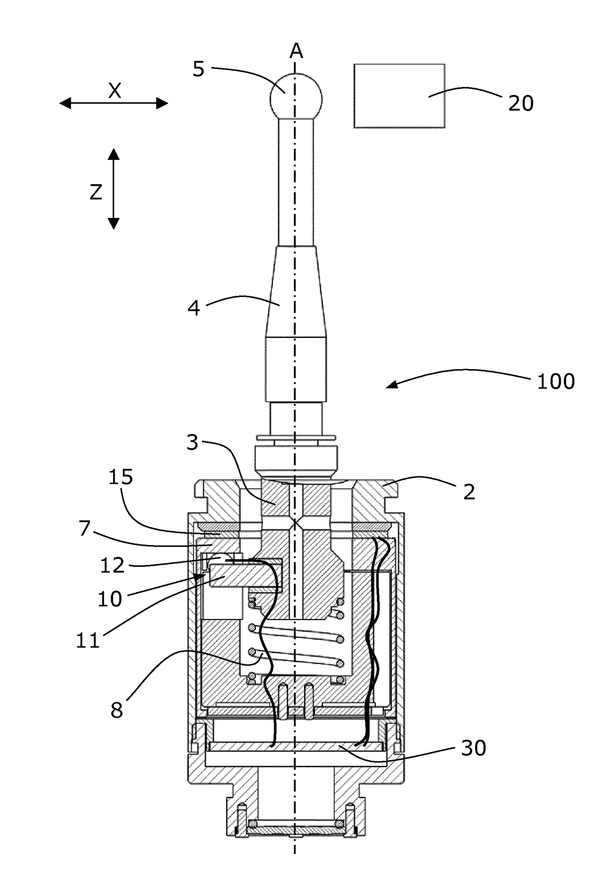
[0020]FIG. 1 shows in a schematic way the section of a touch probe 100 for checking position and / or dimensions of a workpiece 20. In a preferred embodiment of the invention, the probe 100 includes, for example, a support and protective structure or frame 2 that defines a longitudinal axis A, and an armset 3 that is movable with respect to and partly housed in the frame 2. The armset 3 comprises an arm 4 carrying a feeler 5 adapted to touch the workpiece 20 to be checked. A thrust device with a compression spring 8 is placed between the frame 2 and the armset 3, and urges the latter against a rest and locating area 7 of the frame 2.

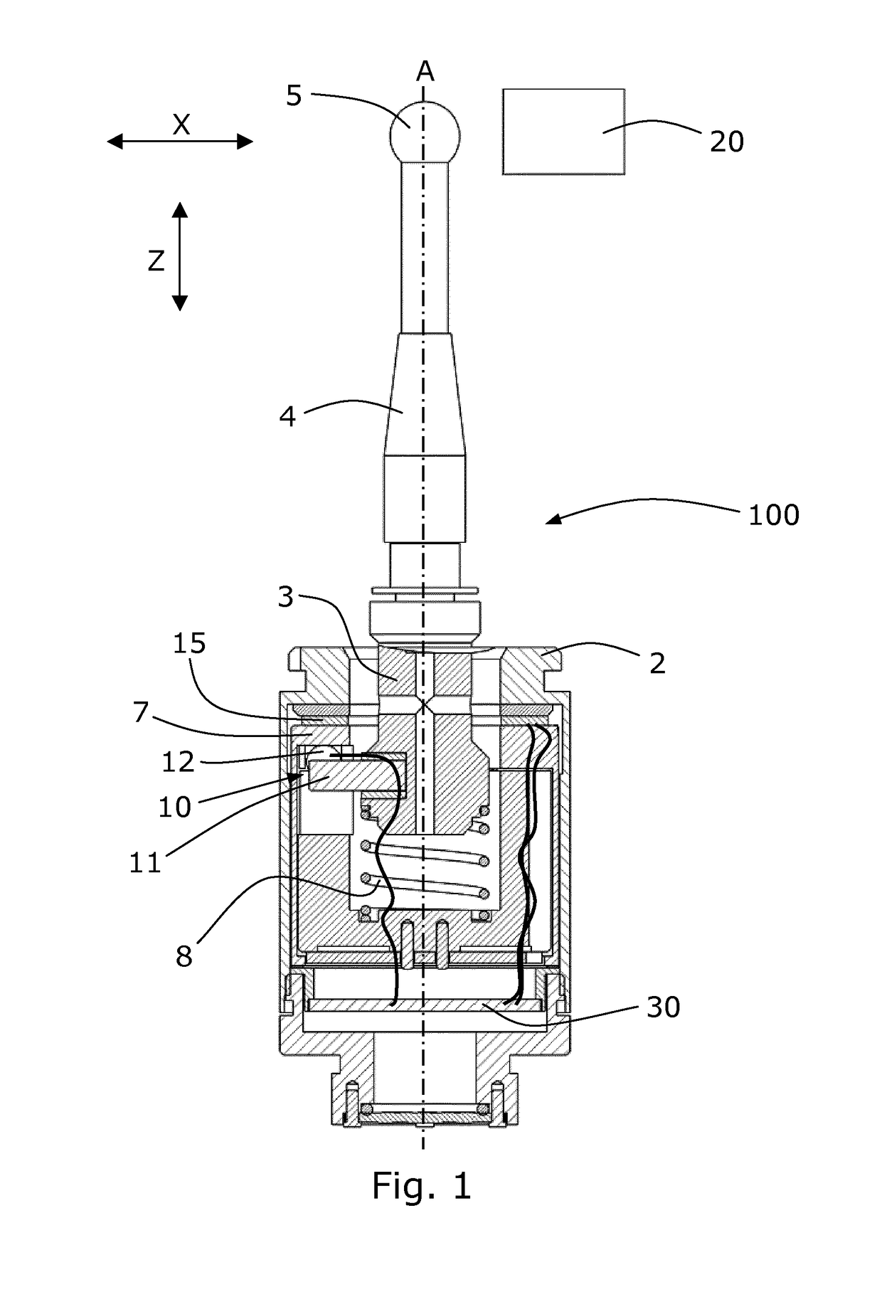
[0021]A constraint and positioning system is arranged between the armset 3 and the frame 2, at the rest and locating area 7. Said constraint and positioning system comprises a rest system with reference mechanical stops 10 defined by the cooperation of mechanical elements of the armset 3 with further mechanical elements of the frame 2, ideally arranged in ...


PUM


Abstract

A probe (100) comprises a frame (2), a movable armset (3) and a processing circuit (30; 30′) for processing signals. The processing circuit is able to individually detect the state of contacts (13) defined by the cooperation between mechanical elements of the armset and mechanical elements of the frame, that is the closing or opening of the contacts, and provide a signal indicative of a rest position of the probe when it detects no more than one open contact. A method for processing signals uses said circuit in order to provide a signal indicative of a rest position of the probe. The circuit and the method for processing signals are advantageously implemented for processing the output signals of a touch probe adapted to check dimensions or position of a workpiece in coordinate measuring machines and machine tools.

Description

TECHNICAL FIELD[0001]The present invention relates to a touch probe for checking position and / or dimensions of a workpiece, comprising a support and protective frame with a rest and locating area, an armset that is movable with respect to and partly housed in the support and protective frame, comprising an arm carrying a feeler adapted to touch the workpiece to be checked, a thrust device adapted to urge the armset against the rest and locating area, a constraint and positioning system, arranged between the armset and the support and protective frame at the rest and locating area, comprising a rest system with reference mechanical stops and contacts that are closed when mechanical elements of the armset cooperate with mechanical elements of the support and protective frame, the reference mechanical stops being adapted to define a rest position of the touch probe, and a processing circuit adapted to detect the state of the contacts and to provide a signal indicative of the rest posit...

Claims


Application Information

Patent Timeline
Patent Type & Authority Patents(United States)
IPC IPC(8): G01B7/00G01B7/012G01B21/04G01B5/012
CPCG01B7/012G01B21/047G01B5/012
Inventor PADOVANI, ROBERTODONDI, DANIELE
Owner MARPOSS SPA
Why Eureka
Try Eureka