
Voxelization of a mesh

a mesh and mesh technology, applied in the field of image generation, can solve the problems of increasing the workload of processing machines and further consuming the computer resources used to present images

Active Publication Date: 2018-01-23
BIOSENSE WEBSTER (ISRAEL) LTD
View PDF6 Cites 35 Cited by
  • Summary
  • Abstract
  • Description
  • Claims
  • Application Information

AI Technical Summary

Problems solved by technology

The manipulation becomes more computer intensive as the resolution, size and numbers of colors in the image increases.
In time critical fields, such as during a surgical procedure, the manipulation may be required to be in substantially real-time, leading to further demands on computer resources used to present the image.

Method used


Image

  • Voxelization of a mesh
  • Voxelization of a mesh
  • Voxelization of a mesh

Examples


Embodiment Construction

Overview

[0028]Manipulation of surface images, such as rotating, translating, magnifying, and / or de-magnifying the images is typically computer intensive. Furthermore, as the resolution of images and number of colors in the images increase, the computing power needed to perform the manipulations in a timely manner also needs to increase. Rather than provide such increased computing power, prior art systems may reduce the resolution of the image, reduce the number of colors, and / or increase the time taken for manipulating the image.

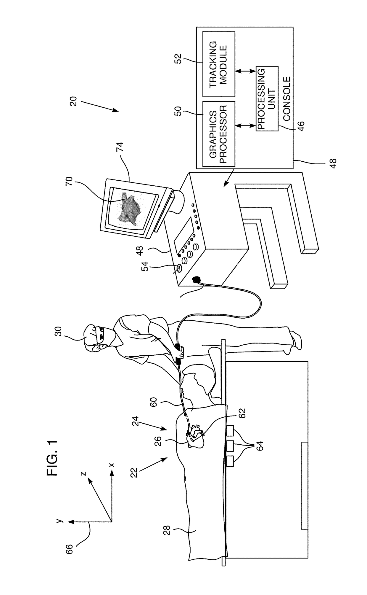
[0029]Embodiments of the present invention take a different tack, by providing the increased computing power needed for quick manipulations of images having a high resolution. The increased computer power is provided in the form of a dedicated graphics processor. As is known in the art, a graphics processor has a highly parallel structure, which makes it more effective than general purpose processing units for processing large blocks of data.

[0030]In embodi...


PUM


Abstract

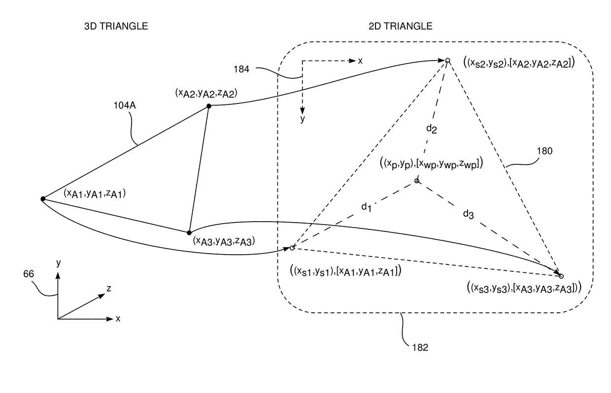
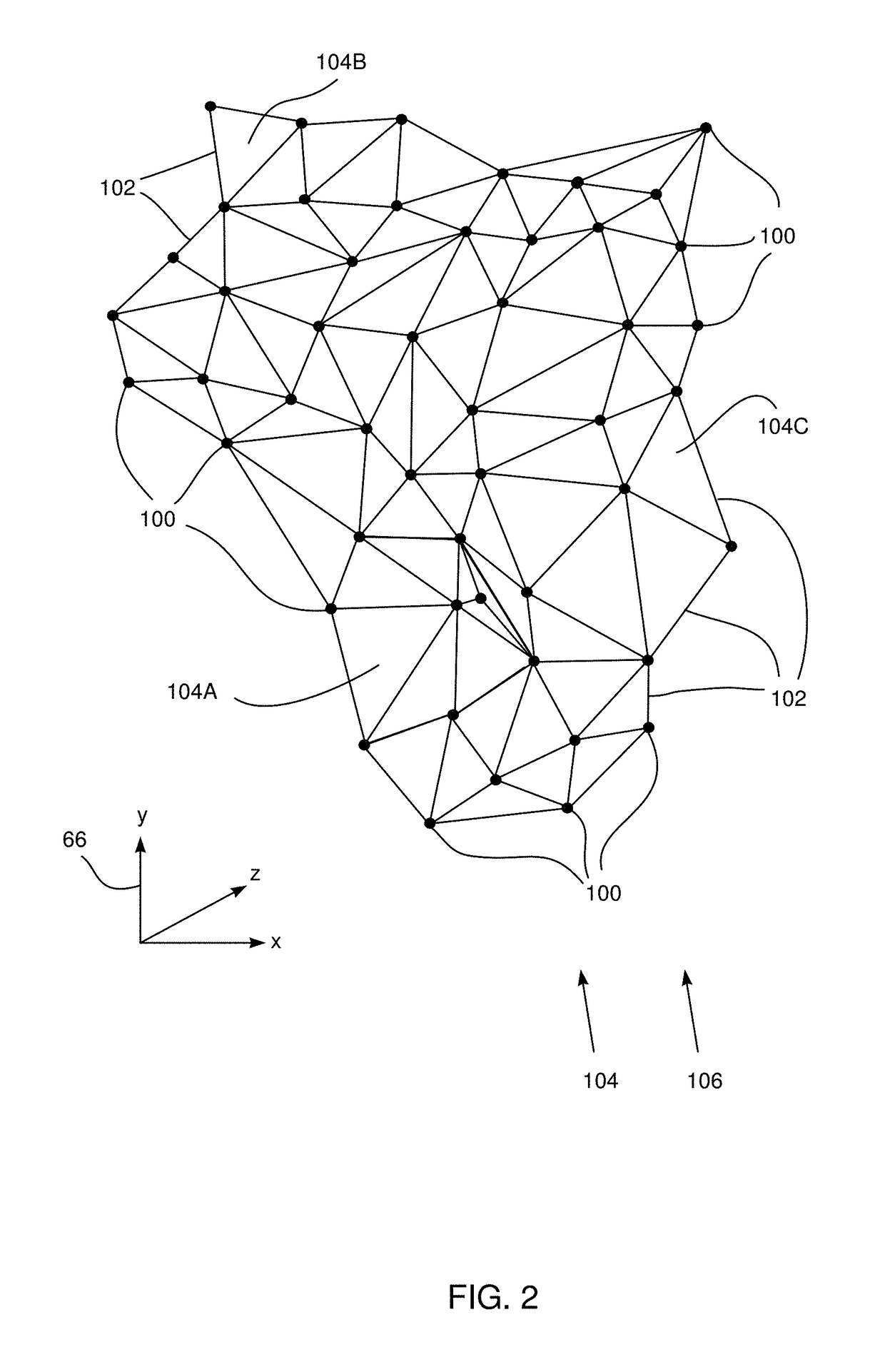
A method for 3D rendering, including receiving a group of 3D triangles defining a mesh of a surface, each 3D triangle in the group having 3D vertices with respective 3D coordinates, and transforming each 3D triangle into a 2D triangle having 2D vertices corresponding respectively to the 3D vertices, each 2D vertex having respective 2D pixel coordinates and a triplet of pixel attributes corresponding to the 3D coordinates of a corresponding 3D vertex. Each 2D triangle is passed to a graphics processor, which treats the triplet of pixel attributes of each 2D vertex as interpolatable values. The graphics processor computes respective triplets of interpolated pixel attributes for pixels within each 2D triangle by interpolation between the pixel attributes of the 2D vertices, and a 3D image of the surface is rendered by converting the interpolated pixel attributes computed by the graphics processor into voxel coordinates in the 3D image.

Description

FIELD OF THE INVENTION[0001]The present invention relates generally to image generation, and specifically to efficient generation of an image from a mesh.BACKGROUND OF THE INVENTION[0002]In many fields it is important to be able to manipulate images in a timely manner. The manipulation becomes more computer intensive as the resolution, size and numbers of colors in the image increases. In time critical fields, such as during a surgical procedure, the manipulation may be required to be in substantially real-time, leading to further demands on computer resources used to present the image. In some cases, in order to maintain real-time behavior, the quality of the image may be reduced, for example by reducing the resolution of the image or by reducing the number of colors in the image.SUMMARY OF THE INVENTION[0003]An embodiment of the present invention provides a method for three-dimensional (3D) rendering, including:[0004]receiving a group of 3D triangles defining a triangular mesh of ...

Claims


Application Information

Patent Timeline
Patent Type & Authority Patents(United States)
IPC IPC(8): G06T17/20A61B5/06G06T15/00G06T15/08A61B34/10G06T17/00
CPCG06T17/205A61B5/062A61B34/10G06T15/08G06T17/00G06T17/20G06T15/005A61B2034/105G06T1/20G06T19/20G06T15/00
Inventor ZAR, LIORKATZ, NATAN SHARONCOHEN, BENJAMIN
Owner BIOSENSE WEBSTER (ISRAEL) LTD
Learn More