
Enhanced turbocompressor startup

a turbocompressor and startup technology, applied in the direction of pump control, non-positive displacement fluid engine, climate sustainability, etc., can solve the problems of tripping the driver, unstable turbocompressor startup, slow startup, etc., to minimize the overall energy required and safe start the effect of the turbocompressor

Active Publication Date: 2018-01-30
COMPRESSOR CONTROLS CORP
View PDF17 Cites 6 Cited by
  • Summary
  • Abstract
  • Description
  • Claims
  • Application Information

AI Technical Summary

Benefits of technology

The technical effect of this patent is to provide a way to start up a turbocompressor safely while using less energy overall.

Problems solved by technology

As all those of ordinary skill in this art know, surge is an unstable operating condition of a turbocompressor encountered at generally low flow rates.
This results in slower startup and, possibly, tripping of the driver due to power overload.
An electric motor driver may trip on thermal overload due to a current being too high for too long a duration.

Method used


Image

  • Enhanced turbocompressor startup
  • Enhanced turbocompressor startup
  • Enhanced turbocompressor startup

Examples


Embodiment Construction

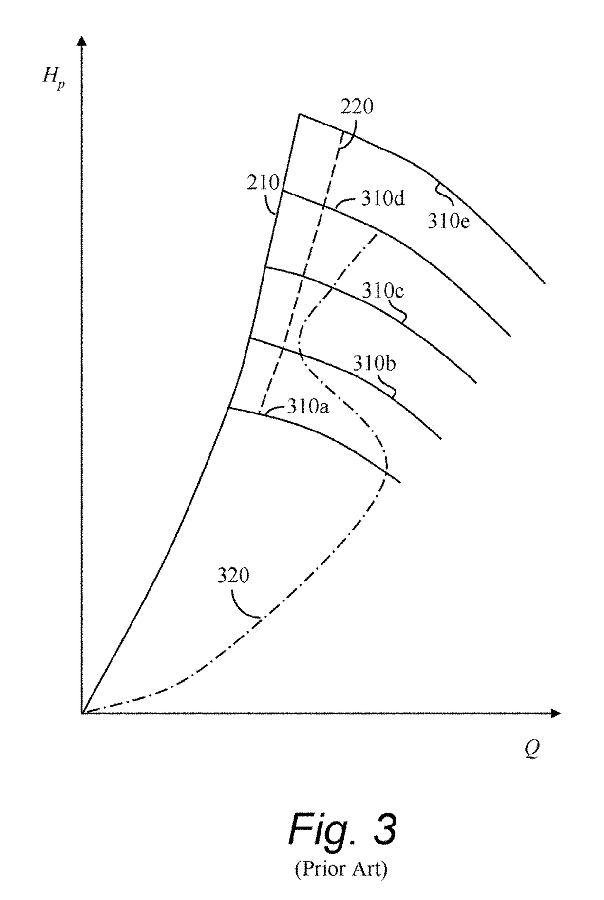
[0030]A typical compressor performance map in Hp-Q coordinates is shown in FIG. 4. Here, Hp is polytropic head and Q is volumetric flow rate—usually in the suction. The map of FIG. 4 comprises solid-line curves of constant rotational speed 310a-310e and dashed-line curves of constant shaft power 410a-410e. As is clear from the relationship between the curves of constant rotational speed 310a-310e and the curves of constant shaft power 410a-410e, at a given rotational speed, the required shaft power decreases as the operating point moves toward the surge limit 210. To avoid overpowering the compressor driver 110, 710 (see FIG. 7) an operating point trajectory 520, shown in FIG. 5, running as near the surge limit 210 as possible, should be used. The short-dashed curve 510 represents a surge control line—a line set a predetermined distance from the surge limit line 210 toward the stable operating region, thus providing a safety margin for the antisurge control system.

[0031]As those of ...


PUM


Abstract

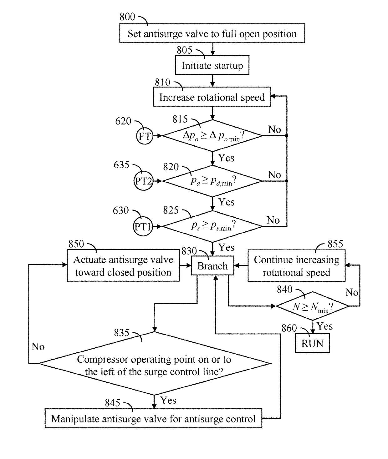
A control method and apparatus for startup of turbocompressors to avoid overpowering a driver of the turbocompressor. In a first embodiment, the control system monitors input signals from transmitters of various control inputs. When the input signals exceed threshold values, the control system begins to close the antisurge valve. In a second embodiment, the antisurge valve begins to close after a predetermined time measured from the time startup is initiated. In both embodiments, the antisurge valve continues to ramp closed until the compressor has reached its operating zone, or until the compressor's operating point reaches a surge control line, at which point the antisurge valve is manipulated to keep the compressor from surging.

Description

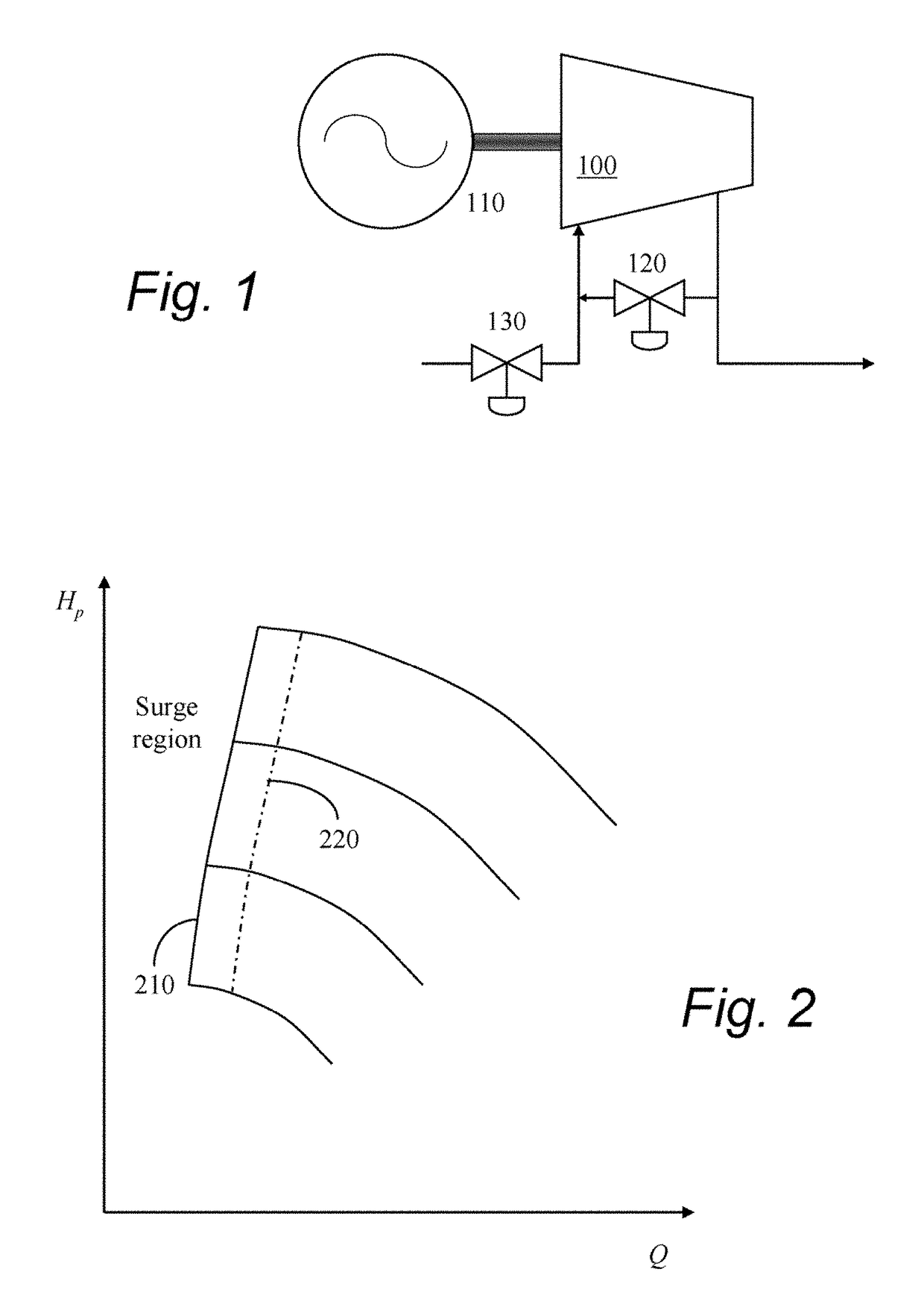
CROSS REFERENCE TO RELATED APPLICATIONS[0001]This application is a Continuation of U.S. patent application Ser. No. 12 / 128,265, filed May 28, 2008, this application is also a Continuation-In-Part of U.S. patent application Ser. No. 13 / 743,418 filed Jan. 17, 2013, now U.S. Pat. No. 8,540,498 issued Sep. 24, 2013, which is a Divisional of U.S. patent application Ser. No. 12 / 047,938, filed Mar. 13, 2008, now U.S. Pat. No. 8,360,744, issued Jan. 29, 2013, Priority is claimed from all of the above identified applications and all are incorporated herein by reference in their entirety.BACKGROUND OF THE INVENTION[0002]Field of the Invention[0003]The present invention relates generally to a control scheme. More particularly the present invention relates to a method and apparatus for reducing a shaft power required when starting up a turbocompressor by manipulating the compressor's antisurge recycle valve.[0004]Background Art[0005]As shown in FIG. 1, a turbocompressor 100, whether axial or ce...

Claims


Application Information

Patent Timeline
Patent Type & Authority Patents(United States)
IPC IPC(8): F04D27/02
CPCF04D27/0292F04D27/0261Y02B30/70F05D2260/85
Inventor MIRSKY, SAULJACOBSON, WAYNEMCWHIRTER, JEFF
Owner COMPRESSOR CONTROLS CORP
Learn More