
Universal electric motor with variable air gap

a technology of electric motors and air gaps, applied in the direction of dynamo-electric machines, electrical apparatus, magnetic circuits, etc., can solve the problems of general complex motors, electromagnetic leakage and the resulting pollution, and achieve the effect of reducing leakage and less electromagnetic pollution

Inactive Publication Date: 2002-10-22
PATARCHI ALBERTO
View PDF3 Cites 13 Cited by
  • Summary
  • Abstract
  • Description
  • Claims
  • Application Information

AI Technical Summary

Benefits of technology

The aim of the present invention therefore is to eliminate the aforementioned drawbacks, providing a constructively simple electric motor, which presents reduced leakage and lesser electromagnetic pollution with respect to traditional motors of the same kind.
Yet another aim of the present invention is to provide an electric motor which can be started safely in both directions of rotation.
Among the other advantages noted are excellent efficiency levels thanks to the perfect closure of the magnetic flow between stator and rotor. The total power expended for the rotation of the motor is reduced since the power provided by the electromagnet to repel the permanent magnet from one rotor tooth is substantially identical to that provided by the attraction of the magnet to the rotor tooth of the following step.
The motor according to the invention has particularly simple components, and therefore its cost is reduced.
The motor according to the invention can be applied, instead of to a rotor made of ferromagnetic material, to a rotor whose teeth are polar expansions permanently magnetized with the same polarity as the permanent magnet of the excitation system, or opposite thereto. In this case, the motor functions by repulsion or, respectively, by attraction and for the offset required for its motion it is the electromagnet winding that is off-center with respect to the polar pitch, to the right or to the left of the desired direction of rotation. Therefore, the power of the electromagnet serves to win the repulsion or attraction force of the permanent magnet and to provide the desired power to the motor shaft.

Problems solved by technology

Such motors are generally complex from the constructive standpoint.
Moreover, since the windings are energized according to many periodically alternating phases, such motors give problems in terms of electromagnetic leakage and of the resulting pollution.

Method used


Image

  • Universal electric motor with variable air gap
  • Universal electric motor with variable air gap
  • Universal electric motor with variable air gap

Examples


second embodiment

In reference to FIG. 9, the motor according to the invention is shown. The rotor 1a is axially elongated and presents three teeth indicated generally as 10a. The electromagnet 21a presents an armature 24a and a winding 25a. The electromagnet armature 24a and the permanent magnet 23a are correspondingly elongated and laterally face, with their air gap, the rotor 1a.

In reference to FIG. 10, a third embodiment of the motor according to the invention is shown. The rotor 1b is considerably flattened with respect to the motor of the second embodiment and, similarly, it presents three teeth indicated generically as 10b. The electromagnet 21b presents an armature 24b and a winding 25b. The electromagnet armature 24a and two permanent magnets 23b laterally face, with their air gap, the rotor 1b.

fourth embodiment

In reference to FIG. 11, the motor according to the invention is shown. The rotor 1c is an annular track 6, made for instance of plastic material, bearing inserts 3 made of ferromagnetic material. As shown, the rotor 1c is integral with a blade 4 centrally provided with a support element 5 for the rotation of the rotor. The excitation system is represented schematically by an electromagnet 21c, presenting an armature 24c and a winding 25c, a permanent magnet 23c and a position detector 26c.

fifth embodiment

In reference to FIG. 12, the motor according to the invention is shown. The rotor 1d has a single attraction step, presenting a single ferromagnetic tooth 10d and a neutral step lid, of the same mass density as the tooth 10d.


PUM


Abstract

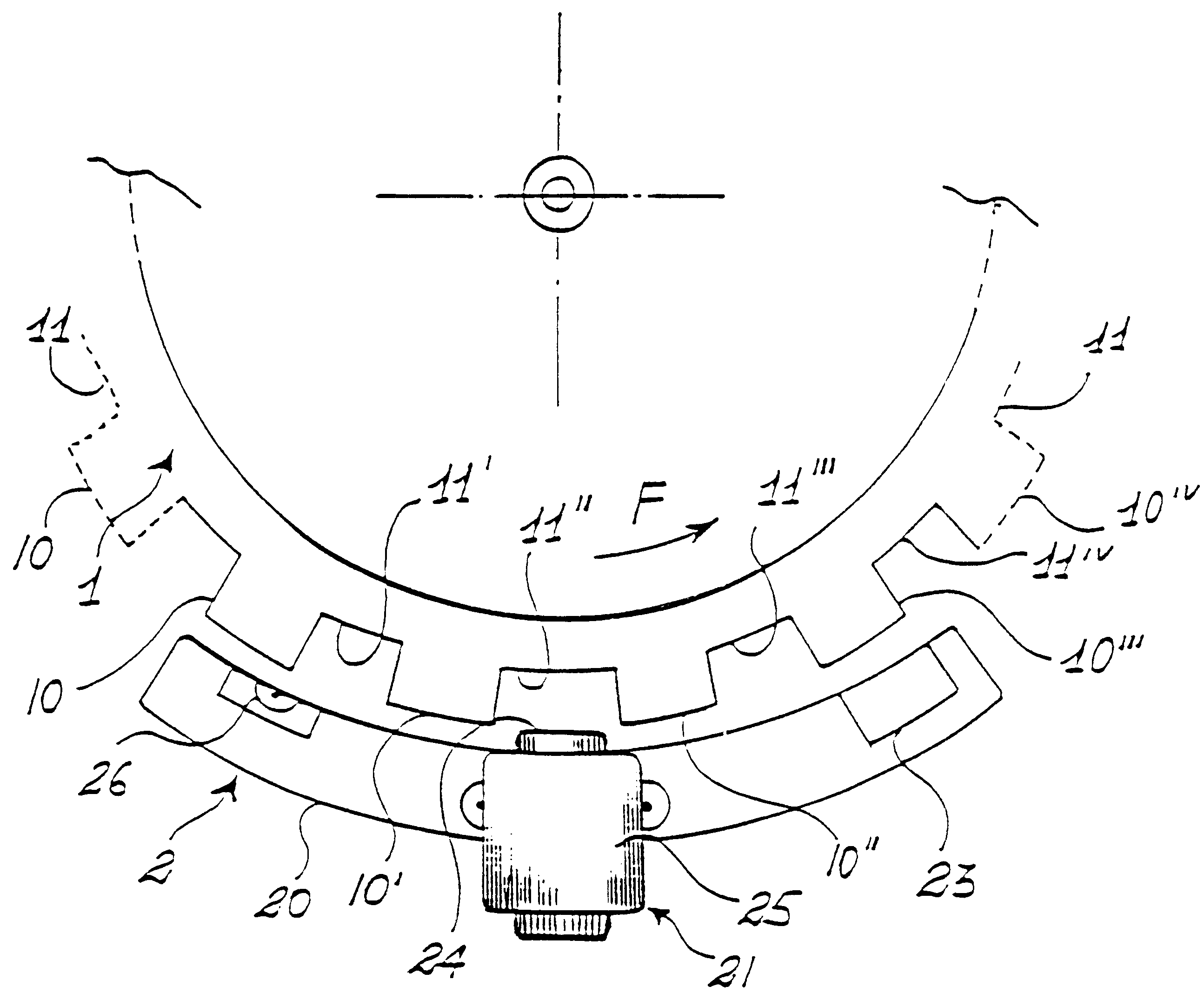
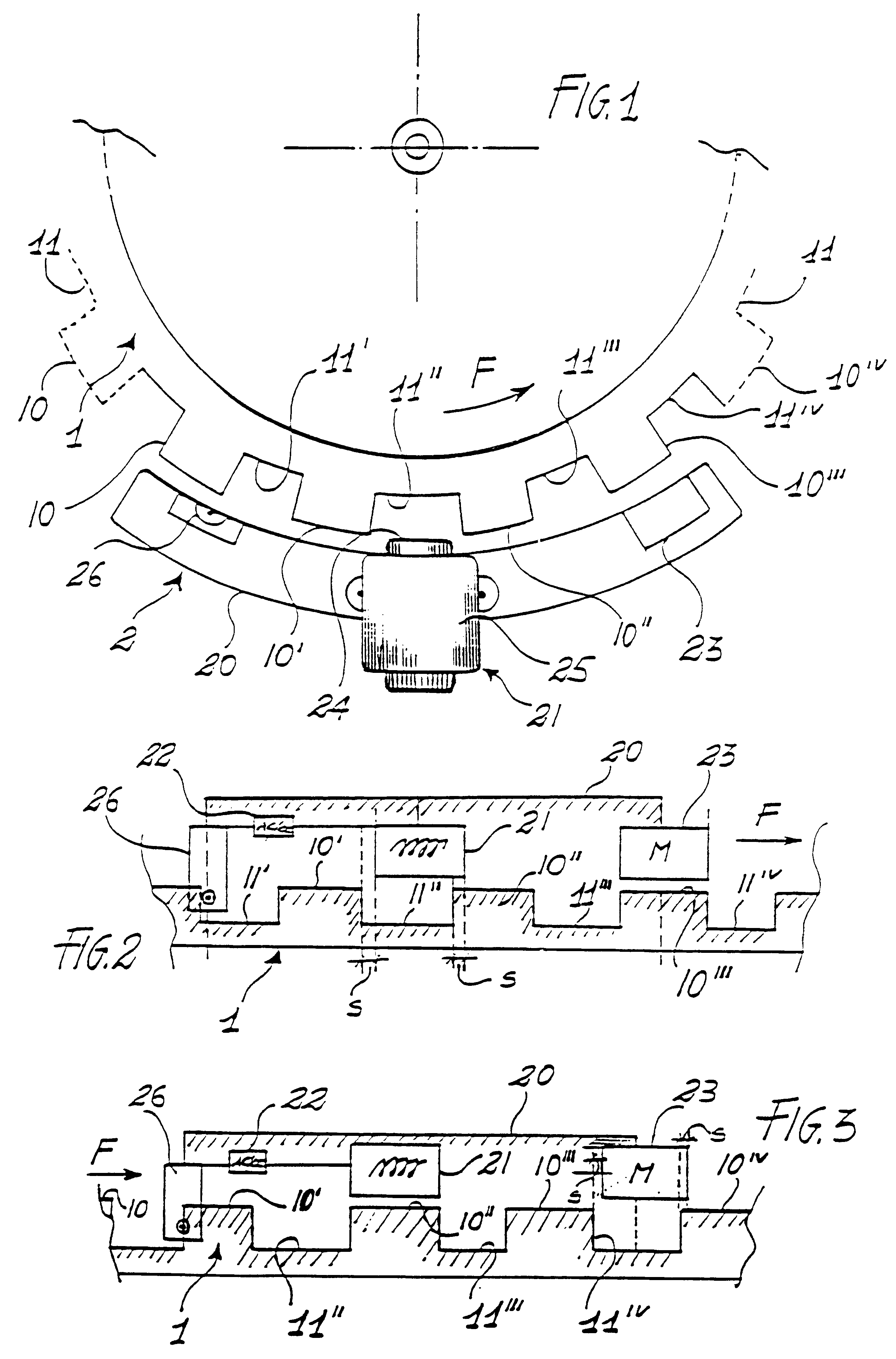
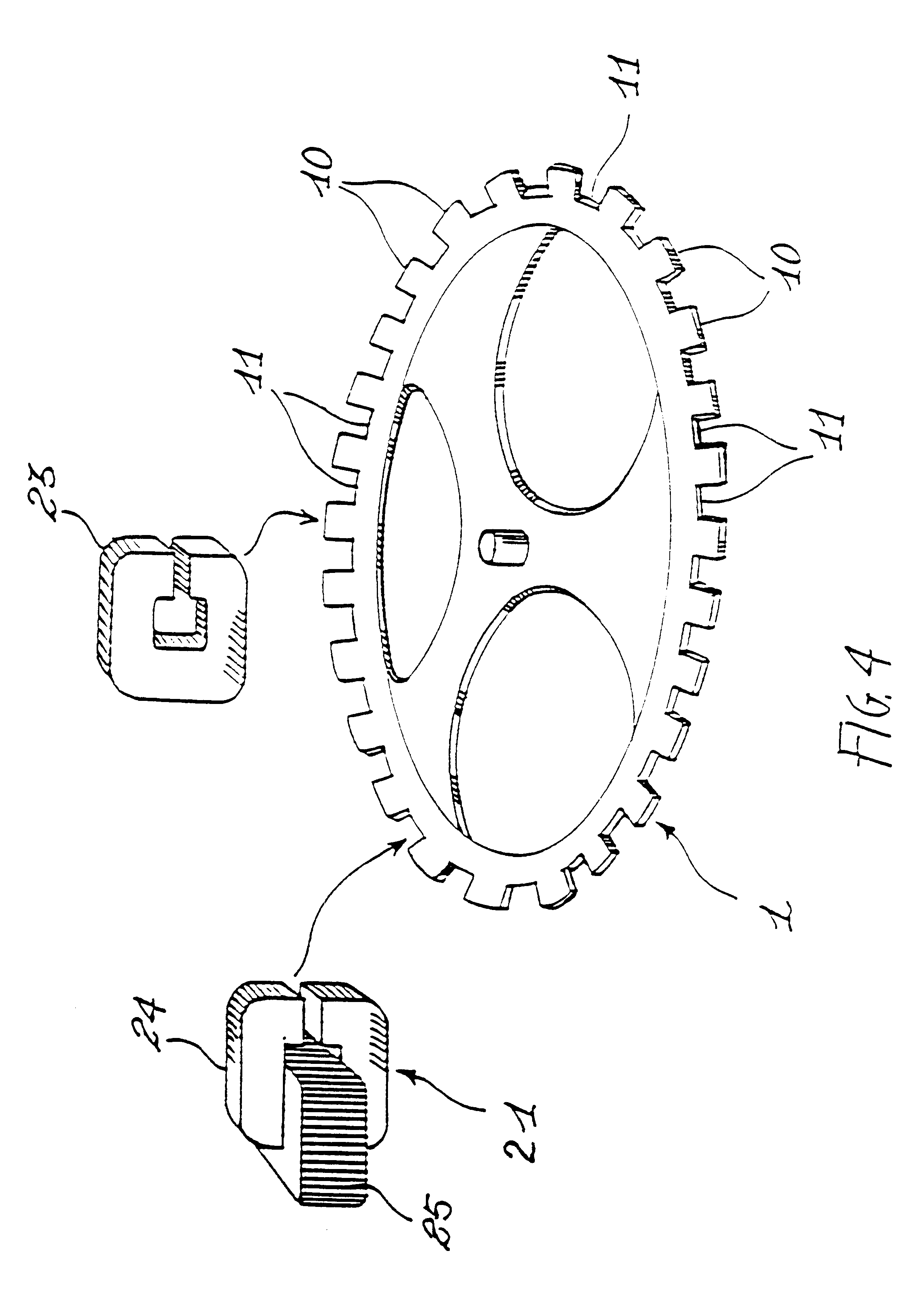
The present invention relates to a universal electric motor with variable air gap. It has a rotor (1) with on or more attraction steps and a stator (2) provided with an excitation system. The excitation system comprises, mounted consecutively distanced on a stator support (20) facing the rotor (1), at least an electromagnet (21), provided with an armature (24) and with a winding (25), a control circuit (22), provided with a position detector (26) for supply power to the electromagnet, and a permanent magnet (23). The electromagnet, and a permanent magnet (23). The electromagnet (21) and the permanent magnet (23) are fastened onto the stator support (20) to excite the rotor alternatively, and in adjustable positions the direction of rotation of the rotor itself.

Description

The present invention relates to a universal electric motor with variable air gap.Stepped electrical motors with variable reluctance are already known, having a rotor formed by a core with cylindrical shape, whose teeth are positioned along the lateral surface, and a coaxial stator having a plurality of excitation windings in a number different from that of the teeth, as shown by FR. No. 2 275 925, for instance.Such motors are generally complex from the constructive standpoint. Moreover, since the windings are energized according to many periodically alternating phases, such motors give problems in terms of electromagnetic leakage and of the resulting pollution.DISCLOSURE OF INVENTIONThe aim of the present invention therefore is to eliminate the aforementioned drawbacks, providing a constructively simple electric motor, which presents reduced leakage and lesser electromagnetic pollution with respect to traditional motors of the same kind.A further aim of the present invention is to ...

Claims


Application Information

Patent Timeline
IPC IPC(8): H02K21/38H02K21/00H02K19/06
CPCH02K21/44
Inventor PATARCHI, ALBERTO
Owner PATARCHI ALBERTO
Learn More