Torque coupling

a technology of torque coupling and coupling plate, which is applied in the direction of couplings, slip couplings, mechanical equipment, etc., can solve the problems of prone wear and tear of torque couplings, hollow wheels, and the wear and tear of clamped elements that engage with running surfaces, so as to achieve less prone to wear and tear

Active Publication Date: 2018-01-30
HILTI AG
View PDF25 Cites 0 Cited by
  • Summary
  • Abstract
  • Description
  • Claims
  • Application Information

AI Technical Summary

Benefits of technology

[0003]It is an object of the present invention to provide a torque coupling that is less prone to wear and tear.
[0004]The torque coupling according to the invention has a shaft, a hollow shaft and a plurality of levers. The bearings of the levers are non-rotatably connected to the shaft and the levers are spring-loaded so as to be pressed against the hollow shaft. The levers are bent from a steel strip. In long-term tests, the bent steel strip proves to be less prone to wear and tear than levers that are made of a solid piece of the same material. A possible explanation for this is seen in the lower surface roughness stemming from the different production methods. The relatively lesser inertia could also translate into less stress in the case of dynamic load changes. The levers can be bent from spring steel.

Problems solved by technology

Torque couplings are subject to a great deal of wear and tear during operation.
In particular, the running surfaces of the hollow wheel and the clamped elements that engage with the running surface tend to wear out.

Method used


Image

  • Torque coupling
  • Torque coupling

Examples


Embodiment Construction

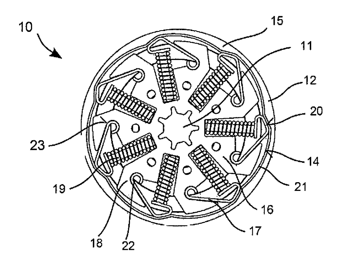
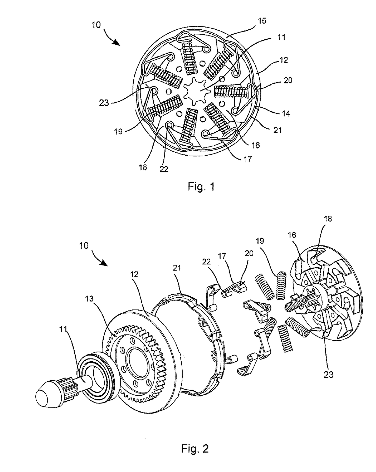
[0010]FIG. 1 shows an embodiment of a torque coupling 10 by way of an example; FIG. 2 is an exploded view of the torque coupling 10. The torque coupling 10 comprises a shaft 11 and a hollow shaft 12. The shaft 11 can have a star-shaped cross section. A gear wheel 13 can be attached to the hollow shaft 12 or else an outer circumference of the hollow shaft 12 can be configured as a gear wheel 13. An inside 14 of the hollow shaft 13 is profiled. The profile can be formed, for example, by several projections 15 that protrude in the radial direction with respect to the shaft 11.

[0011]The shaft 11 has a hub 16. The hub 16 has several levers 17 that are rotatably attached to the hub 16. Springs 19 deflect the levers 17 in the radial direction against the inside 14 of the hollow shaft 12.

[0012]A torque transmission between the shaft 11 and the hollow shaft 12 takes place via the spring-loaded levers 17 that engage with the profiled inside 14 of the hollow shaft 12. The torque transmission i...


PUM


Abstract

The torque coupling has a shaft, a hollow shaft and a plurality of levers. The bearings of the levers are non-rotatably connected to the shaft and the levers are spring-loaded so as to be pressed against the hollow shaft. The levers are bent from a steel strip.

Description

BACKGROUND[0001]The present invention relates to a torque coupling as known, among other things, from German laid-open document DE 199 29 833 A.[0002]Torque couplings are subject to a great deal of wear and tear during operation. In particular, the running surfaces of the hollow wheel and the clamped elements that engage with the running surface tend to wear out.SUMMARY OF THE INVENTION[0003]It is an object of the present invention to provide a torque coupling that is less prone to wear and tear.[0004]The torque coupling according to the invention has a shaft, a hollow shaft and a plurality of levers. The bearings of the levers are non-rotatably connected to the shaft and the levers are spring-loaded so as to be pressed against the hollow shaft. The levers are bent from a steel strip. In long-term tests, the bent steel strip proves to be less prone to wear and tear than levers that are made of a solid piece of the same material. A possible explanation for this is seen in the lower s...

Claims


Application Information

Patent Timeline
Patent Type & Authority Patents(United States)
IPC IPC(8): F16D7/04
CPCF16D7/048
Inventor STROISSNIGG, HORSTMANSCHITZ, ERWINLUDWIG, MANFREDKAIBACH, WERNERSCHALLERT, MANFREDMOESSNANG, FRANZKRISTEN, FERDINAND
Owner HILTI AG
Why Eureka
Try Eureka