Electrical supply into wind turbine hub

a technology of wind turbine hub and electrical supply, which is applied in the direction of motors, rotary current collectors, engine fuctions, etc., can solve the problems of insufficient contact between slip rings and high power current transfer, slip rings may be exposed to heavy wear and may need regular maintenance or even replacement, and slip rings may not always provide sufficient contact. good for high power current transfer

Active Publication Date: 2018-02-27
VESTAS WIND SYST AS
View PDF18 Cites 0 Cited by
  • Summary
  • Abstract
  • Description
  • Claims
  • Application Information

AI Technical Summary

Benefits of technology

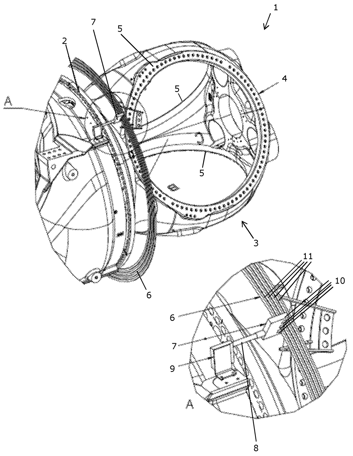
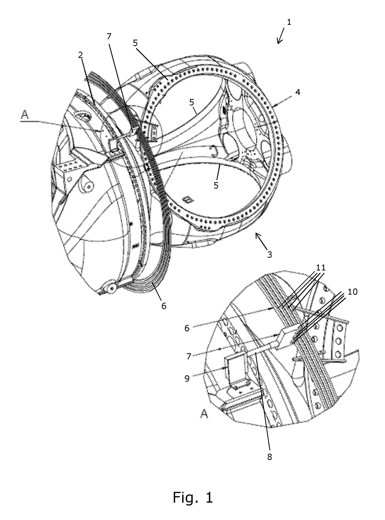
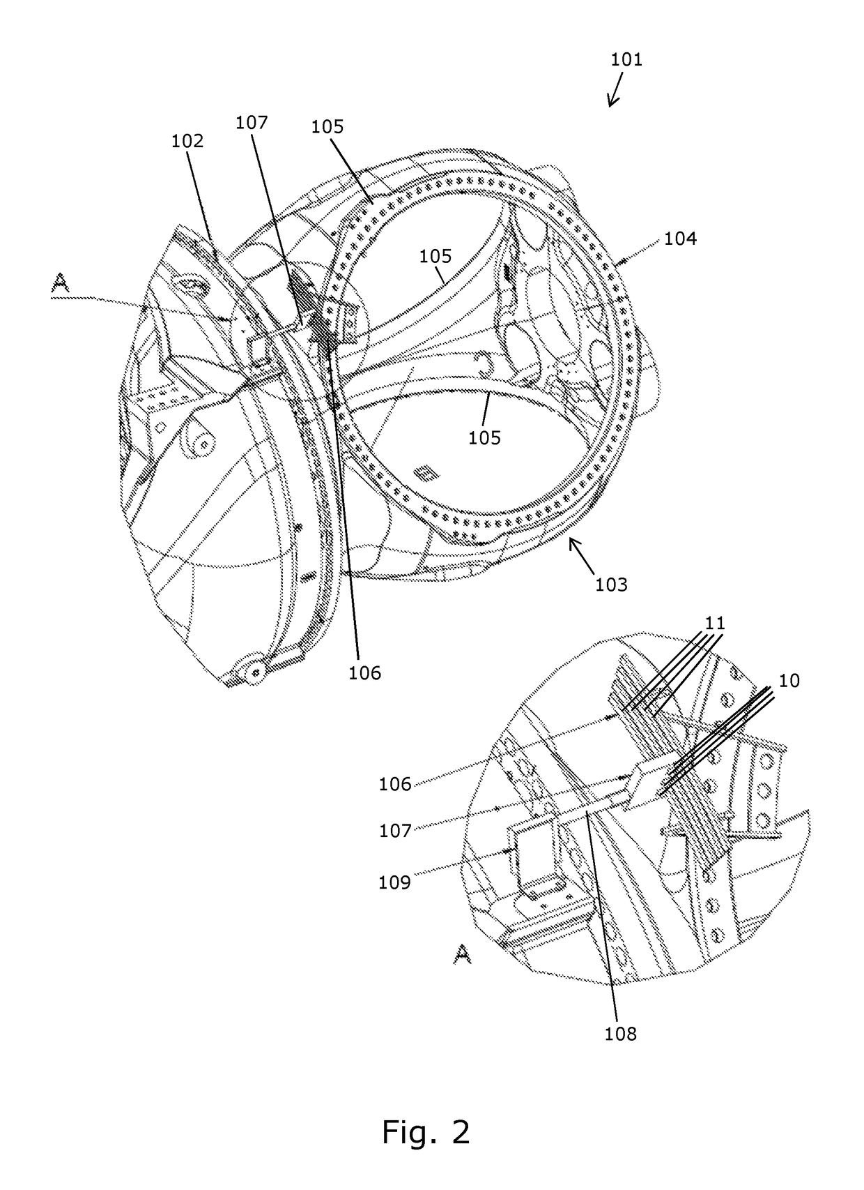
[0009]By providing a supply structure with a switch for connection and disconnection of the electrical connection between the nacelle and the rotor, the wear of the supply structure for supplying electrical power from the nacelle to the rotor can be decreased, as it is possible to establish the electrical connection only when needed.
[0010]Furthermore, the wear may be lowered even more, as it is possible to break off the electrical contact when electrical power is not needed in the rotor.
[0031]By shaping the contact faces so that they form matching surface imprints, one of the contact faces may at the same time provide guidance for the other one of the contact faces, thereby facilitating establishment of the electrical connection between the contact faces.
[0032]In order to ensure that the rotor is stopped so that the switch can be connected and thereby establish an electrical connection between the nacelle and the rotor, the wind turbine may comprise a control unit responsible for stopping rotation of the rotor at the requested position. The control unit may control braking of the rotor based on, e.g. information on the position of the rotor, and thus the position of the switch, the rotational speed of the rotor, and / or the deceleration of the rotor, thereby allowing for an automatic breaking of the rotor.
[0033]To limit the requirement of exact positioning of the contact faces relative to each other, when stopping rotation of the rotor before changing from the disconnected mode to the connected mode, it may be an advantage if the contact faces are of different size. Thus, the smaller one of the contact faces may be brought into contact with the larger one of the connecting faces over a large area, thereby limiting the positioning requirement.

Problems solved by technology

Due to the increasing size of the wind turbine, the slip ring needs to be of a considerable size.
Furthermore, the slip ring may be exposed to heavy wear and may thus need regular maintenance or even replacement.
Moreover, the slip ring may not always provide sufficiently good contact for transfer of high power current.

Method used


Image

  • Electrical supply into wind turbine hub
  • Electrical supply into wind turbine hub
  • Electrical supply into wind turbine hub

Examples


Embodiment Construction

[0004]It is an object of embodiments of the invention to provide a wind turbine having an improved electrical supply structure for supplying electrical power from the nacelle to the rotor.

[0005]According to a first aspect, the invention provides a wind turbine comprising a nacelle, a rotor comprising at least one blade attached to a hub, the rotor being rotatably connected to the nacelle about an axis of rotation, and an electrical supply structure for supplying electrical power from the nacelle to the rotor, wherein the supply structure comprises a switch having a connected mode in which the nacelle and the rotor are electrically connected, and a disconnected mode in which the nacelle and the rotor are electrically disconnected, and wherein the switch is adapted to change from the disconnected mode to the connected mode when the rotor does not rotate.

[0006]In the present context the term ‘wind turbine’ should be interpreted to mean an apparatus which is capable of transforming ener...


PUM


Abstract

The invention provides a wind turbine including a nacelle, a rotor having at least one blade attached to a hub, and an electrical supply structure for supplying electrical power from the nacelle to the rotor. The rotor is rotatably connected to the nacelle about an axis of rotation. The supply structure comprises a switch which has a connected mode in which the nacelle and the rotor are electrically connected, and a disconnected mode in which the nacelle and the rotor are electrically disconnected. Furthermore, the switch is adapted to change from the disconnected mode to the connected mode when the rotor does not rotate.

Description

FIELD OF THE INVENTION[0001]The present invention relates to a wind turbine comprising an electrical supply structure for supplying electrical power from the nacelle to the rotor.BACKGROUND OF THE INVENTION[0002]In the wind power industry there is a tendency to produce wind turbines of increasing size, whereby the size of the individual parts of the wind turbines also increase. Traditionally, electrical power is transferred from the nacelle to the rotor by use of a slip ring as the rotor is rotatably connected to the nacelle. Thus, the slip ring can be used to transfer electrical power from the stationary nacelle to the rotating rotor. Due to the increasing size of the wind turbine, the slip ring needs to be of a considerable size.[0003]Furthermore, the slip ring may be exposed to heavy wear and may thus need regular maintenance or even replacement. Moreover, the slip ring may not always provide sufficiently good contact for transfer of high power current.DESCRIPTION OF THE INVENTIO...

Claims


Application Information

Patent Timeline
Patent Type & Authority Patents(United States)
IPC IPC(8): F03D1/06F03D9/25H01R39/42F03D80/00F03D80/40F03D80/80H01R39/10F03D7/04H01R39/26
CPCF03D7/042F03D1/0691F03D9/25F03D9/255F03D80/00F03D80/40F03D80/82H01R39/10H01R39/26H01R39/42F03D1/0675Y02E10/726F05B2260/40F05B2260/76F05B2270/602Y02E10/721Y02E10/72
Inventor BAUN, TORBEN FRIISNEUBAUER, JESPER LYKKEGAARD
Owner VESTAS WIND SYST AS
Why Eureka
Try Eureka