Cutter assembly having a screw-locking device

a screw-locking device and cutter technology, which is applied in the field of cutter assembly, can solve the problems of insufficient locking force of conventional screw-locking devices, inability to position blades firmly and stably, and easy wear of threaded rods and the inner surface of blade holders, and achieve excellent locking for

Inactive Publication Date: 2017-04-18
SDI CORPORATION
View PDF11 Cites 0 Cited by
  • Summary
  • Abstract
  • Description
  • Claims
  • Application Information

AI Technical Summary

Benefits of technology

[0007]The main objective of the invention is to provide a cutter assembly having a screw-locking device to provide an excellent locking force.
[0009]With such an arrangement, a firm and stable locking force can be provided to the slider and the blade with the engagement between the engaging segments on the bottom of the blade holder and the locking bolt. The blade will not be moved unintentionally while a large force is applied to the blade. In addition, wear between the locking bolt and the blade holder can be prevented, a firm and stable locking force is provided to the blade, and the service life of the cutter assembly can be also prolonged.

Problems solved by technology

Thus, the locking force of the conventional screw-locking device is not sufficient, and the slider and the blade are easily moved when a specific pushing or pulling force is applied to the cutter.
Thus, the blade cannot be positioned firmly and stably.
In addition, the threaded rod and the inner surface of the blade holder are easily worn off due to the abutment between the threaded rod and the inner surface of the blade holder, and depressions or scratches are easily formed on the inner surface of the blade holder.
Accordingly, the conventional screw-locking device cannot provide a sufficient locking force to the blade.

Method used


Image

  • Cutter assembly having a screw-locking device
  • Cutter assembly having a screw-locking device
  • Cutter assembly having a screw-locking device

Examples


Embodiment Construction

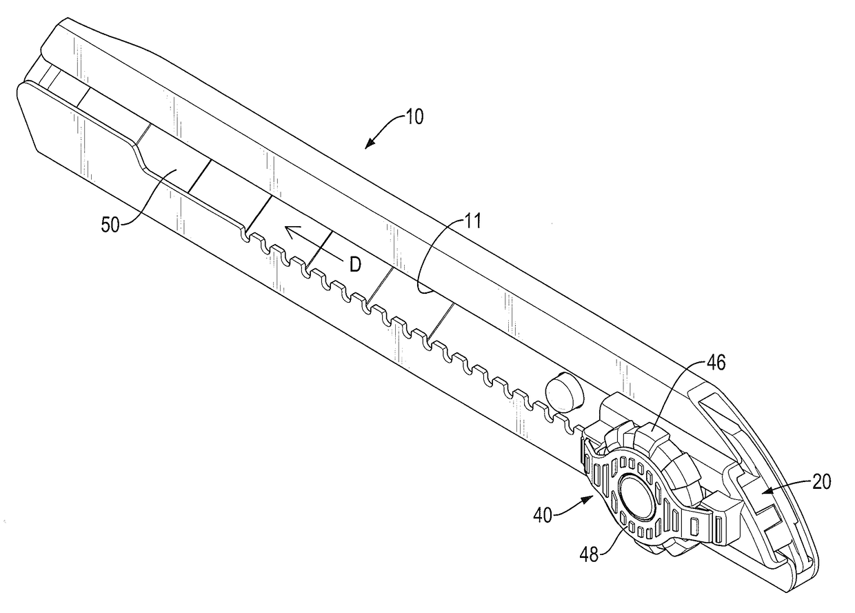
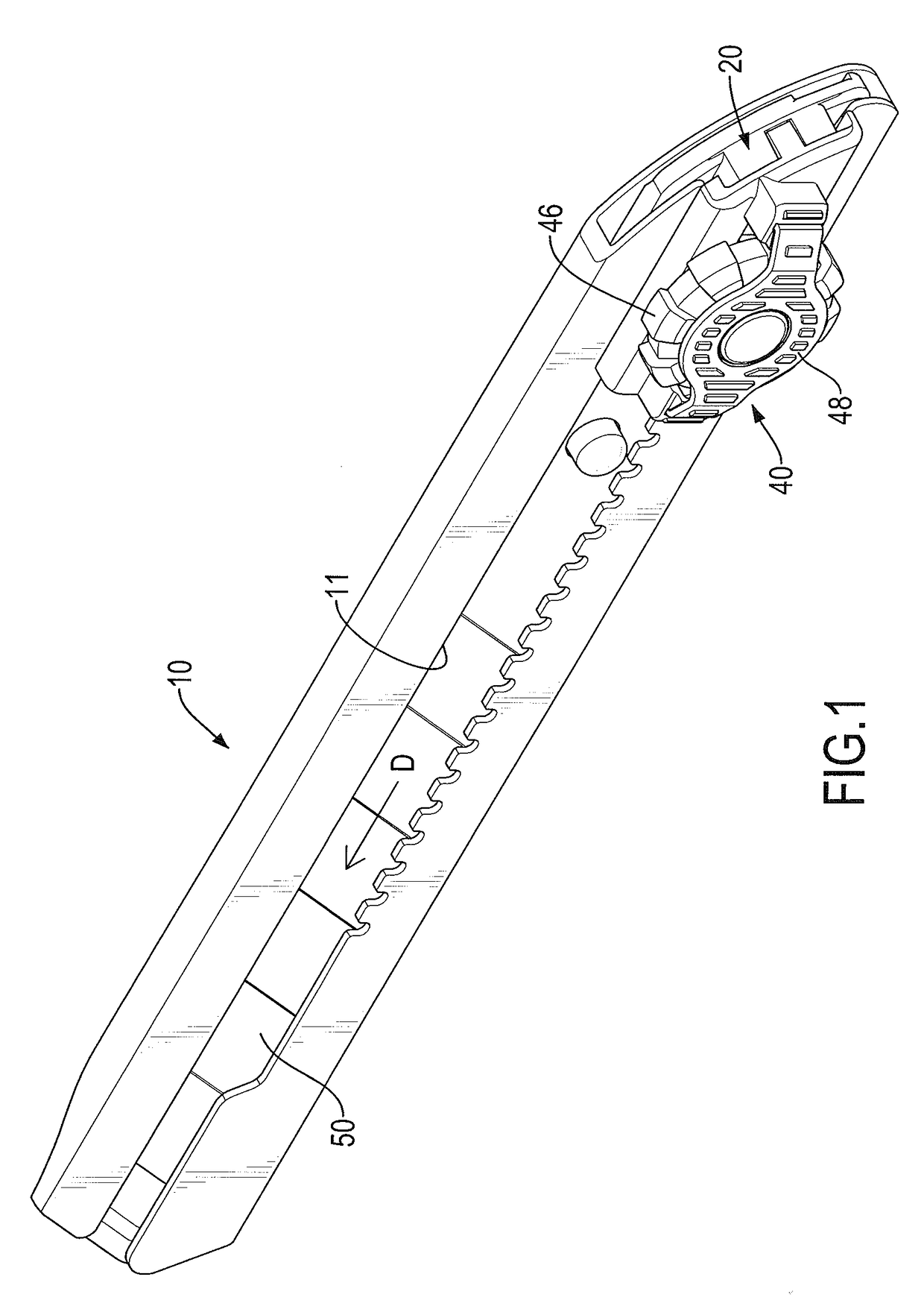
[0022]With reference to FIGS. 1 to 4, a first embodiment of a cutter assembly in accordance with the present invention comprises a blade holder 10, a slider 20, an automatic locking device 70, a screw-locking device 40 and a blade 50. The blade 50 is moveably mounted in the blade holder 10.

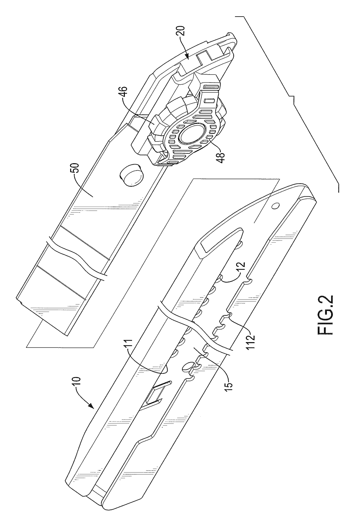
[0023]The blade holder 10 comprises multiple engaging segments 12 disposed on a bottom 15 of the blade holder and arranged along a moving direction D of the blade 50. Preferably, the bottom 15 of the blade holder 10 has a flat inner surface. The engaging segments 12 are arranged in a line and may be holes, recesses or ribs arranged at intervals. The shapes of the engaging segments 12 may be round or square. In the first embodiment, the engaging segments 12 are engaging holes formed through the blade holder 10. A guiding channel 11 is defined in a side of the blade holder 10 and has two side edges. Multiple positioning segments 112 are formed in one of the two side edges of the guiding channel 11 a...


PUM


Abstract

A cutter assembly has a blade holder, a blade, a slider and a screw-locking device. The blade is moveably mounted in the blade holder and has a moving direction. The blade holder has a bottom and multiple engaging segments disposed on the bottom along the moving direction of the blade. The slider is mounted slidably on the blade holder and connected to the blade. The screw-locking device is mounted on the slider and has a locking bolt and a locking sleeve screwed with each other. The locking bolt has an end selectively engaging at least one of the engaging segments.

Description

BACKGROUND OF THE INVENTION[0001]1. Field of the Invention[0002]The present invention relates to a cutter assembly and, more particularly, to a cutter assembly having a screw-locking device.[0003]2. Description of Related Art[0004]A retractable cutter is applied to cut paper or wooden sheets and substantially comprises a blade holder, a blade and a slider. The slider is mounted on the blade holder. The blade is mounted slidably in the blade holder and is connected to the slider. When the slider is pushed, the blade is moved relative to the blade holder to extend out of the blade holder to enable a user to cut an object by the cutter. To hold the blade at a desired position with a desired extension length relative to the blade holder and to provide a large positioning force, a screw-locking device is mounted on the slider for cutting a thick or hard object. The conventional screw-locking device substantially comprises a threaded rod mounted on the slider. When the threaded rod is rot...

Claims


Application Information

Patent Timeline
Patent Type & Authority Patents(United States)
IPC IPC(8): B26B3/06B26B5/00
CPCB26B5/001
Inventor PAI, CHENG-YUCHU, YAO-CHIACHEN, CHING-LITSAI, CHOU-CHIEH
Owner SDI CORPORATION
Why Eureka
Try Eureka