Lockout system for energy sources

a technology for energy sources and locks, applied in the field of industrial safety devices, can solve the problems of confusion and disorganization of the general appearance of lockout/tagout equipment, unwieldy and inconvenient use of prior-art kits, and inconvenient us

Active Publication Date: 2018-01-30
GRIFFIN JASON P
View PDF18 Cites 15 Cited by
  • Summary
  • Abstract
  • Description
  • Claims
  • Application Information

AI Technical Summary

Benefits of technology

[0014]Also, workers find it uncomfortable and inconvenient to carry a tag and lock with them while on the job. This inconvenience further discourages workers from following proper lockout / tagout procedure. Since compliance with procedure is essential for workplace safety, the current lockout / tagout equipment leaves room for improvement. Further, no system exists that allows a supervisor to remotely determine which pieces of equipment are locked and by whom. Therefore, what is needed is a lockout system and apparatus that is more convenient and efficient to use by workers.
[0016]It is an objective of the present invention to facilitate compliance with lockout / tagout procedure, therefore improving worker safety and reducing workplace accidents from stored energy sources. The present invention achieves these and other objectives by providing a lockout system and apparatus that includes a hasp assembly and a plurality of tags, where the hasp assembly can be retained in a locked position when one or more tags are received in the hasp assembly.
[0029]Another aspect of the present invention is directed to a method of locking an energy source comprising the steps of providing a hasp assembly defining a plurality of tag slots each defining a lock opening, where the hasp assembly has an openable hasp and a locking bar operable with the openable hasp by moving between a locked position and an unlocked position, the locking bar defining a plurality of notches configured to align with respective ones of the plurality of tag slots when the locking bar is in the locked position; providing a plurality of tags each defining a tag opening and configured to be removably installed in one of the tag slots with a first end portion of the tag sized to be received in one of the notches and the tag opening aligned over a lock opening; moving the locking bar to the unlocked position, thereby opening the openable hasp; installing the hasp through a lock opening on an energy source to be locked; moving the locking bar to the locked position, thereby closing the openable hasp and aligning the notches in the locking bar with the tag slots; installing one or more tags into the hasp assembly with each first end portion received in one of the notches and the tag opening aligned over a corresponding lock opening; providing one or more padlocks each having a padlock hasp sized to extend through the tag opening of a tag and through the corresponding lock opening of a tag slot; and locking one padlock with the padlock hasp extending through the tag opening and the corresponding lock opening, thereby preventing the one of the plurality of tags tag from being removed from the corresponding tag slot, preventing the locking bar from moving to the unlocked position, and locking the hasp in the closed position.

Problems solved by technology

However, these prior-art kits become unwieldy and inconvenient to use especially when multiple workers have locked a machine.
When many workers install locks and tags on a hasp to lock out a piece of equipment, the access to the hasp is restricted and the general appearance of the lockout / tagout equipment is confusing and disorganized.
The jumble of locks and tags is inconvenient to use, sometimes deterring workers from complying with lockout procedures.
Also, it can be difficult to identify all of the workers who have locks on the hasp due to the disorganization of the locks and tags.
Also, workers find it uncomfortable and inconvenient to carry a tag and lock with them while on the job.
This inconvenience further discourages workers from following proper lockout / tagout procedure.
Further, no system exists that allows a supervisor to remotely determine which pieces of equipment are locked and by whom.
Further, no lockout devices of the prior art provide wireless communication between the hasp assembly and a remote database or computer.

Method used


Image

  • Lockout system for energy sources
  • Lockout system for energy sources
  • Lockout system for energy sources

Examples


Embodiment Construction

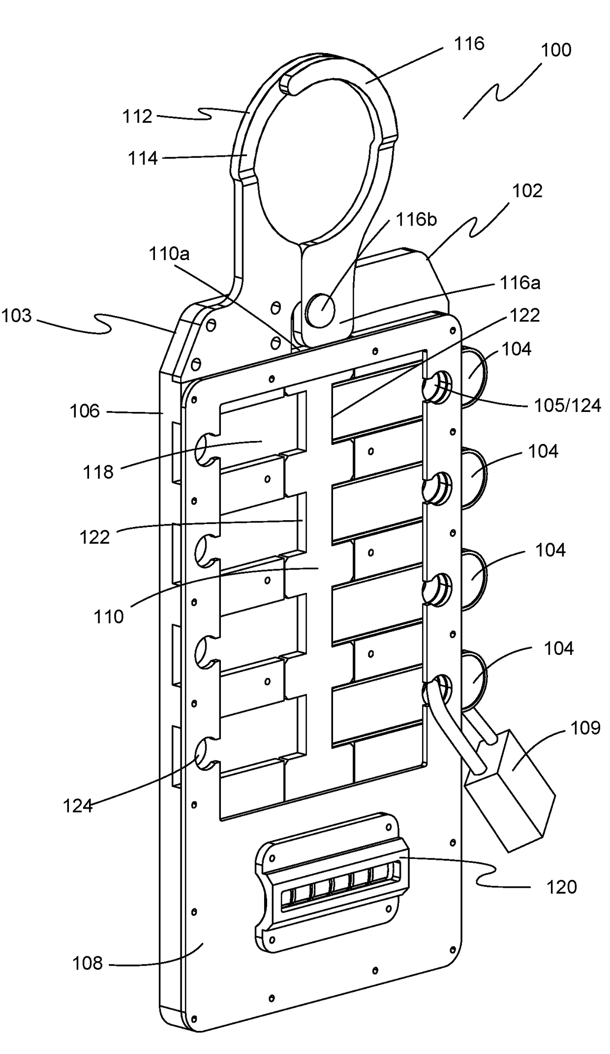
[0046]Exemplary embodiments of the present invention are illustrated in FIGS. 4-14. FIG. 4 illustrates a perspective view of one embodiment of a lockout system 100 of the present invention that includes a lockable hasp assembly 102 and a plurality of tags 104 that can be independently received by and removed from hasp assembly 102.

[0047]One embodiment of hasp assembly 102 has an assembly body 103 that includes a back plate 106 and a front plate 108 attached to the back plate. A locking bar 110 is slidable between back plate 106 and front plate 108. A hasp 112 is attached to the assembly body and includes a first hasp jaw 114 and a second hasp jaw 116 operable between an open position and a closed position in response to movement of the locking bar 110 from an unlocked position to a locked position, respectively.

[0048]As discussed in more detail below, locking bar 110 in one embodiment slides along body 103 in engagement with second hasp jaw 116, thereby causing second hasp jaw 116 t...


PUM


Abstract

A lockout system includes a hasp assembly and a plurality of tags. The hasp assembly has a back plate defining slots each sized and shaped to receive a tag. The back plate and tags each have openings that align when a tag is received in a slot. A first hasp portion on the back plate defines part of a closed loop. A longitudinal locking bar is slidable along the back plate and has notches shaped to receive ends of the tags. Moving the locking bar between an unlocked position and a locked position operates the second hasp portion between an open position and a closed position. In the closed position, the first and second hasp portions complete and define the closed loop, where one or more tags can be installed in slots with the first end of the tag engaging a notch to lock closed the hasp portion.

Description

BACKGROUND OF THE INVENTION[0001]1. Field of the Invention[0002]The present invention relates generally to industrial safety devices. More particularly, the present invention relates to a lockout system and apparatus for use with industrial equipment and energy sources.[0003]2. Description of the Prior Art[0004]Energy sources in machines and equipment is a hazard to workers. Energy sources include electrical, mechanical, hydraulic, pneumatic, chemical, and thermal energy sources. Workers servicing or maintaining machines or equipment must properly control energy sources to avoid accidents. While servicing and maintaining machines and equipment, for example, an unexpected machine startup or release of stored energy can result in serious injury or death to workers. Injuries resulting from a failure to control hazardous energy during maintenance activities can be fatal and include burns, crush injuries, cuts, lacerations, amputations, and bone fractures.[0005]For example, a steam valve...

Claims


Application Information

Patent Timeline
Patent Type & Authority Patents(United States)
IPC IPC(8): E05B65/48E05B41/00E05B43/00E05B51/00E05B63/00E05B63/12E05B37/00H01H9/20E05B65/00G07C9/00E05B67/38E05B39/04E05B47/00
CPCH01H9/20E05B37/0096E05B39/04E05B41/00E05B43/005E05B51/00E05B63/0004E05B63/0052E05B63/0069E05B63/123E05B65/006E05B65/0089E05B65/48E05B67/38G07C9/00309E05B2047/0067E05B2047/0071G07C2009/00769E05B17/226E05B63/143E05B67/32E05B67/383E05B2047/0094G07C9/00896H01H9/281H01H9/283
Inventor GRIFFIN, JASON P.
Owner GRIFFIN JASON P
Why Eureka
Try Eureka