
Subsonic polymeric ammunition

a polymer and subsonic technology, applied in the field of ammunition articles, can solve the problems of reducing accuracy, inconsistent propellant positioning, and inhibiting proper propellant burn, and achieve the effect of reducing the internal volume of the propellant chamber

Active Publication Date: 2018-02-06
TRUE VELOCITY IP HLDG LLC
View PDF120 Cites 200 Cited by
  • Summary
  • Abstract
  • Description
  • Claims
  • Application Information

AI Technical Summary

Benefits of technology

The design ensures consistent propellant burn, improved accuracy, and sufficient chamber pressure to properly cycle firing mechanisms, addressing the limitations of traditional subsonic ammunition while reducing manufacturing complexity and cost.

Problems solved by technology

Unfortunately, this empty volume can cause numerous problems including inhibition of proper propellant burn, inconsistent propellant positioning, reduced accuracy and propellant detonation caused by extremely high propellant burn rates.
Finally, usage of subsonic ammunition, and its attending lower combustion pressures, frequently results in the inability to efficiently cycle semi-automatic or fully automatic weapons where the propellant charge must produce sufficient gas pressure and / or volume to accelerate the projectile and to cycle the firing mechanism.
With a reduced quantity of propellant, subsonic ammunition generally fails to produce sufficient pressure to properly cycle the firing mechanism.
However, the results of such prior attempts to solve the production of reliable subsonic cartridges have failed and let to subsonic rounds that have a larger variation in velocity and variance in accuracy potential.
In addition the use of polymer ammunition results in additional drawbacks, e.g., the possibility of the projectile being pushed into the cartridge casing, the bullet pull being too light such that the bullet can fall out, the bullet pull being too insufficient to create sufficient chamber pressure, the bullet pull not being uniform from round to round, and portions of the cartridge casing breaking off upon firing, causing the weapon to jam or damage, or danger when subsequent rounds are fired or when the casing portions themselves become projectiles.

Method used


Image

  • Subsonic polymeric ammunition
  • Subsonic polymeric ammunition
  • Subsonic polymeric ammunition

Examples


Embodiment Construction

[0023]While the making and using of various embodiments of the present invention are discussed in detail below, it should be appreciated that the present invention provides many applicable inventive concepts that can be embodied in a wide variety of specific contexts. The specific embodiments discussed herein are merely illustrative of specific ways to make and use the invention and do not delimit the scope of the invention.

[0024]To facilitate the understanding of this invention, a number of terms are defined below. Terms defined herein have meanings as commonly understood by a person of ordinary skill in the areas relevant to the present invention. Terms such as “a”, “an” and “the” are not intended to refer to only a singular entity, but include the general class of which a specific example may be used for illustration. The terminology herein is used to describe specific embodiments of the invention, but their usage does not delimit the invention, except as outlined in the claims.

[...


PUM


Abstract

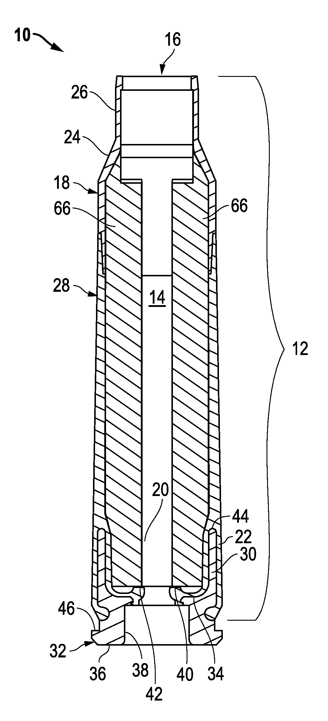
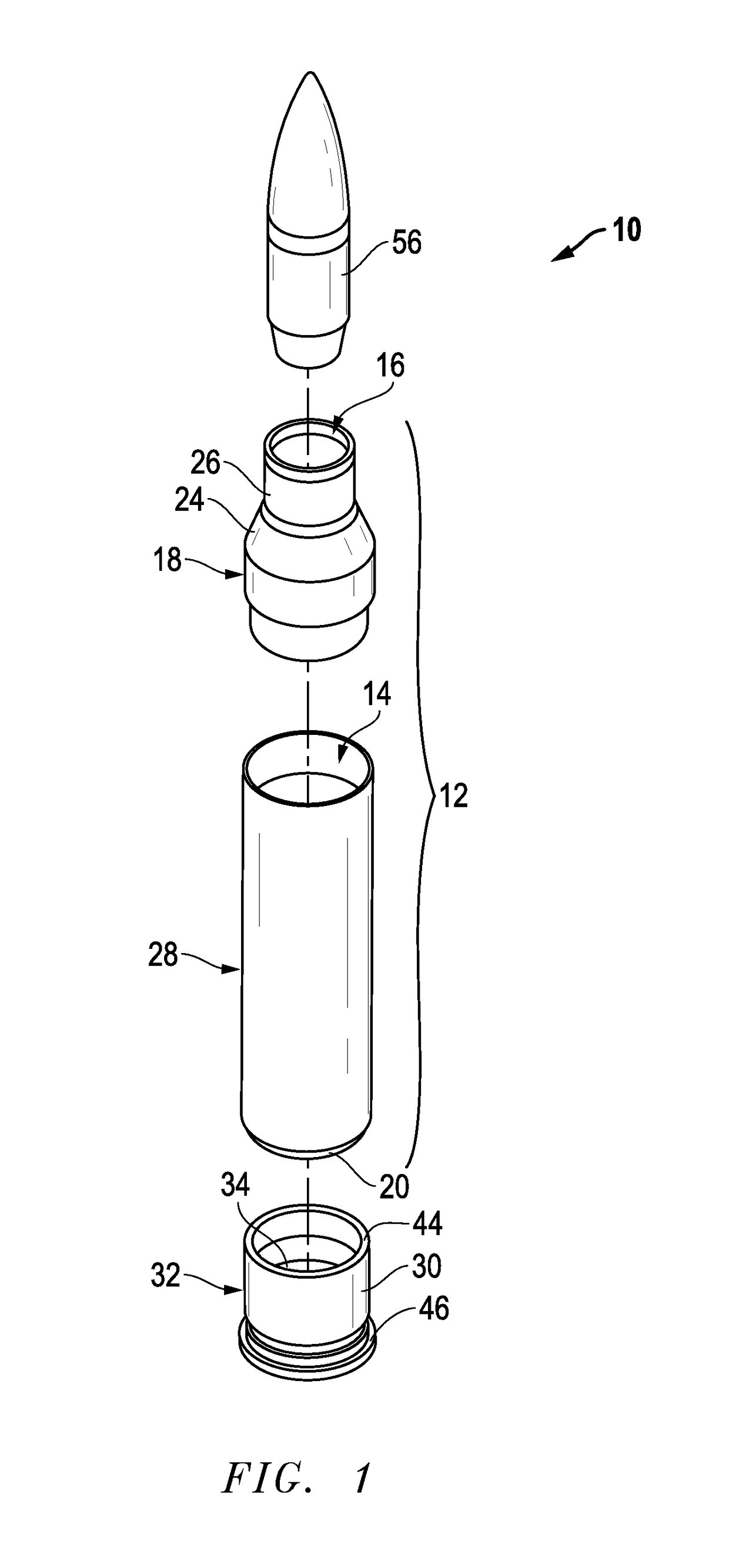
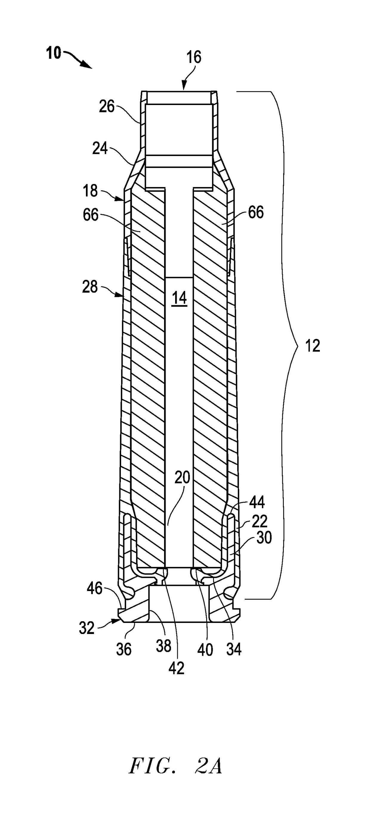
The present invention provides a subsonic ammunition including a polymeric casing body comprising a generally cylindrical hollow polymer body having a body base at a first end thereof and a mouth at a second end to define a propellant chamber; a propellant insert positioned in the propellant chamber to reduce the internal volume of the propellant chamber, wherein the propellant chamber has an internal volume that is at least 10% less than the open internal volume of a standard casing of equivalent caliber; a propellant disposed and confined within the propellant chamber; a primer insert positioned at the body base and in communication with the propellant chamber; a primer disposed in the primer insert in combustible communication with the propellant; and a projectile frictionally fitted in the mouth in combustible communication with the propellant.

Description

CROSS-REFERENCE TO RELATED APPLICATIONS[0001]This application is a Continuation-in-Part of U.S. application Ser. No. 14 / 011,202 entitled “Lightweight Polymer Ammunition Cartridge Casings” filed on Aug. 27, 2013, which is a Divisional of U.S. patent application Ser. No. 13 / 292,843 entitled “Lightweight Polymer Ammunition Cartridge Casings” filed on Nov. 9, 2011 which issued as U.S. Pat. No. 8,561,543 on Oct. 22, 2013, which claims priority to U.S. Provisional Application Ser. No. 61 / 456,664 entitled “Polymer Case Ammunition and Methods of Manufacturing the Same (diffuser and exacter insert)” filed on Nov. 10, 2010. The contents of which are incorporated by reference in their entirety.TECHNICAL FIELD OF THE INVENTION[0002]The present invention generally relates to ammunition articles, and more particularly to subsonic ammunition casings and ammunition casing propellant inserts formed from polymeric materials.STATEMENT OF FEDERALLY FUNDED RESEARCH[0003]Not applicable.INCORPORATION-BY-R...

Claims


Application Information

Patent Timeline
Patent Type & Authority Patents(United States)
IPC IPC(8): F42B5/26F42B5/307F42B5/02F42B5/30
CPCF42B5/26F42B5/307F42B5/30F42B5/02
Inventor BURROW, LONNIE
Owner TRUE VELOCITY IP HLDG LLC
Learn More