Internal fixation devices

a technology of fixation device and inner tube, which is applied in the field of internal fixation device, can solve the problems of unmineralized scar tissue, non-union or pseudo-arthrosis, and non-load-supporting unmineralized scar tissu

Inactive Publication Date: 2010-12-16
SMITH & NEPHEW INC
View PDF28 Cites 791 Cited by
  • Summary
  • Abstract
  • Description
  • Claims
  • Application Information

AI Technical Summary

Benefits of technology

[0016]In an even further aspect, the present disclosure relates to a method of fixating an internal fixation device to a bone including providing an internal fixation device including a cannulated inner portion, an outer portion, at least two C-shaped channels located on the outer portion, the channels located on opposite sides of the device from each other, wherein each channel includes a tab, and a polymer material, the polymer material located within the cannulated inner portion and between the C-shaped channels; inserting the internal fixation device into a bone; and providing the polyme

Problems solved by technology

Problems can arise when a bone fracture or fusion site is not sufficiently stabilized during the healing lifetime.
Excessive interfragmentary motion results in the formation of fibrous, unmineralized scar tissue (resulting in non-union or pseudo-arthrosis) versus regeneration of bone.
The unmineralized scar tissue is not load supporting and skeletal function is lost.
Overtime, however, these stainless steel and titanium fixation devices do not maintain adequate fixation to bone or compression acros

Method used


Image

  • Internal fixation devices
  • Internal fixation devices
  • Internal fixation devices

Examples


example one

[0218]The present example provides a fabrication process for the internal fixation device of the present disclosure, a method of fixating the device to bone, and test results on the fixation strength of the device.

[0219]Sleeves of a polymer composite were manufactured using a copolymer and a filler material. Specifically, 600 g of a copolymer of poly L-lactic acid (PLLA) and poly D-lactic acid (PDLA) having a glycolide component was vacuum dried at a temperature of about 50° C. and a pressure of about 10 millibars for 48 hours. The ratio between the lactide unit and the glycolide unit was 85:15. 300 g of a filler material, namely calcium carbonate, were placed in a 1000 ml glass jar and vacuum dried at about 150° C. and a pressure of about 10 millibars for 48 hours. A dry blend was then produced by mixing the copolymer and calcium carbonate. This blend was then compounded in a prism twin screw extruder to form pellets of a copolymer / calcium carbonate composite. These pellets were pl...

example two

[0222]Two Delrin rods were used to simulate a fractured bone. Ends of the rods were placed adjacent to each other with the point at which the ends of the two rods met being defined as the simulated fracture point. Each rod had a diameter of about 0.75 inches, a length of about 4.3 inches, and a 7 mm diameter through hole that extended the entire length of each rod.

[0223]Fiber reinforced composite rods were then manufactured. PLLA fiber was first made by taking PLLA granules with a nominal intrinsic viscosity of 3.8 and extruding the granules into a fiber. A single screw extruder fitted with a gear pump and a 2 mm spinneret die was used. The extruder also had a provision for air cooling. The extruded fiber was batched on spools for the next processing step. Subsequently, the fiber was progressively stretched at elevated temperatures to produce a final diameter of ca. 100 microns and a draw ratio between about 8 and about 15. The final molecular weight of the drawn fiber was between a...

example three

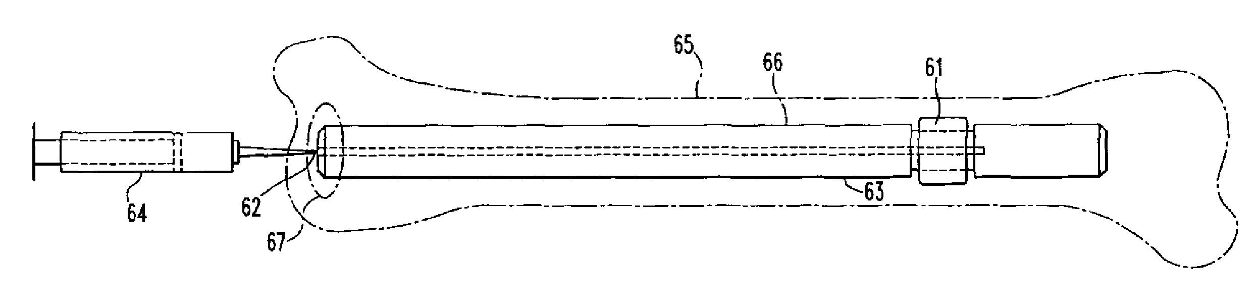
[0228]A die-drawn PLDLA(70 / 30) rod containing 35% wt / wt of calcium carbonate was machined into a plug having a diameter of 13 mm and a length of 25 mm. The plug included a stem having a length of 20 mm and a diameter of 8 mm. The plug was similar in construction to the polymer material shown in FIGS. 53A-53B. A hole of 3 / 16 inch diameter was drilled through the centre the plug. Once machined into these dimensions, a 40 mm length of steel tubing, referred to as a metal sleeve, was inserted into the hole.

[0229]A stainless steel tubing (8 mm ID / 12 mm OD) was generated such that one end of the tubing was profiled to have slots, 3 (6 mm semicircle slots) and 3 (4×8 mm elliptical slots), and the other end was machined to have 3 flat surfaces suitable for an instron to grip. The stem of the plug with metal sleeve was inserted into the end (containing the slots) of the stainless steel tubing, to form a construct, and this construct was placed into the canal of a section of femur, approximat...


PUM


Abstract

The present disclosure relates to an internal fixation device including an interface portion, a polymer material coupled to the interface portion, wherein the polymer material includes at least one feature on a surface of the polymer material, and means for allowing adequate expansion of the polymer material on each side of the bone fracture site. A method of fixating the internal fixation device to a bone and other internal fixation devices and methods for fixating are also disclosed.

Description

CROSS-REFERENCE TO RELATED APPLICATIONS[0001]This application is a PCT International Application claiming priority to U.S. Patent Application No. 60 / 894,505 filed on Mar. 13, 2007, U.S. Patent Application No. 60 / 912,845 filed on Apr. 19, 2007, U.S. Patent Application No. 60 / 912,738 filed on Apr. 19, 2007, U.S. Patent Application No. 60 / 912,740 filed on Apr. 19, 2007, and U.S. Patent Application No. 60 / 989,113 filed on Nov. 19, 2007, the disclosures of which are incorporated herein by reference in their entirety.BACKGROUND OF THE INVENTION[0002]1. Field of the Invention[0003]The present invention relates to internal fixation devices for use in bone fracture repair and more specifically, an internal fixation devices that include a polymer material for improved device stabilization and fracture fixation.[0004]2. Related Art[0005]Problems can arise when a bone fracture or fusion site is not sufficiently stabilized during the healing lifetime. Depending on the nature of the fracture, int...

Claims


Application Information

Patent Timeline
IPC IPC(8): A61B17/58
CPCA61B17/0642A61B17/7225A61B17/7275A61B17/744A61B17/8004A61L27/446A61B17/8052A61B17/866A61B17/8695A61B2017/00867A61B2017/0412A61B17/8047A61B2017/00287A61B2017/00871
Inventor AUSTIN, GENE EDWARDBETTENGA, MASON JAMESEVANS, DAVID L.BRUMFIELD, DAVID L.FABER, HENRY B.FARRAR, DAVID F.HALL, MICHAEL ANDREWMONTES DE OCA BALDERAS, HORACIORAINS, JAMES K.ROSE, JOHNBROWN, MALCOLM
Owner SMITH & NEPHEW INC
Why Eureka
Try Eureka