Rock Bolt

a technology of rock bolts and axial conduits, applied in the field of rock bolts, can solve the problems of large fraction of rock bolts having axial conduits made of fiberglass reinforced plastic damaged and/or destroyed, and cannot be removed from coal, etc., to achieve the effect of reducing the size of the excavated pi

Inactive Publication Date: 2012-08-30
HILTI AG
View PDF5 Cites 6 Cited by
  • Summary
  • Abstract
  • Description
  • Claims
  • Application Information

AI Technical Summary

Benefits of technology

[0007]The problem addressed by one or more embodiments of the present invention is that of providing a rock bolt which possesses sufficient capacity for expansion and tensile strength, and can be cut to enable simplified separation of the excavated pieces of the rock bolt.

Problems solved by technology

The plastic reinforced with fiberglass only expands to a minimal degree when the axial conduit is subjected to tensile forces in the rock, and also possesses low resistance to compression and to shearing forces.
Due to the low resistance to compression and shearing of the material, a large fraction of the rock bolts having the axial conduit made of fiberglass reinforced plastic are damaged and / or destroyed during the installation thereof due to the compression forces and / or shearing forces involved.
These rock bolts are extracted together with the coal, but then cannot be removed from the coal, or can only be removed with very great difficulty.
Rock bolts having an axial conduit made of steel are generally not used to secure coal seams because they cannot be cut, and / or have sharp edges following excavation of the coal.
The rock bolts having an axial conduit made of steel cut up the conveyor belts or destroy other devices used in coal mining, thereby leading to high costs and interruptions.
However, these rock bolts possess insufficient properties with respect to mechanical considerations of expansion, resistance to compression, and resistance to shearing.
Rock bolts having axial conduits made of steel pose the disadvantage that they cause damage to conveyor belts and other equipment of the mine during excavation of the coal.

Method used


Image

  • Rock Bolt
  • Rock Bolt
  • Rock Bolt

Examples


first embodiment

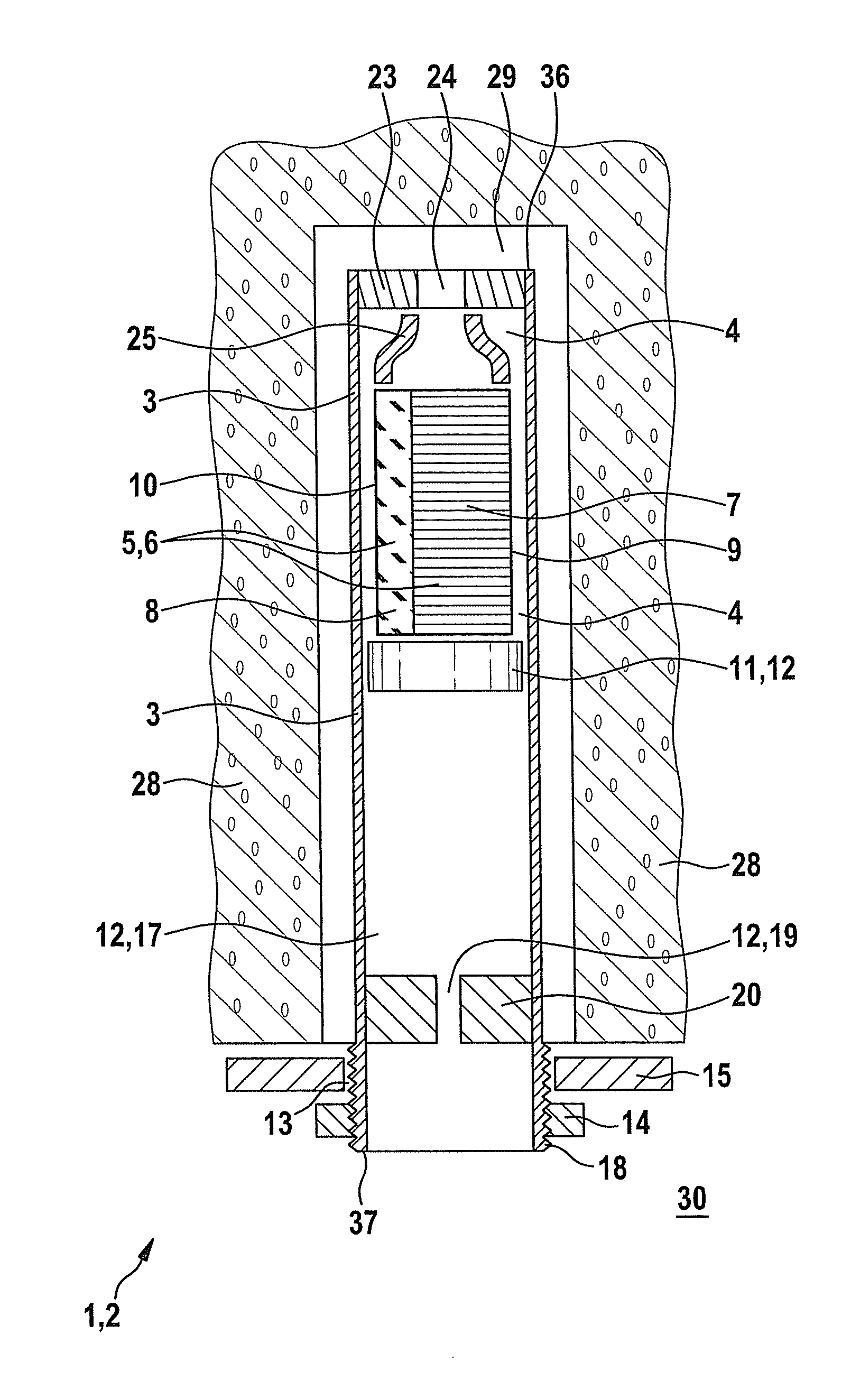
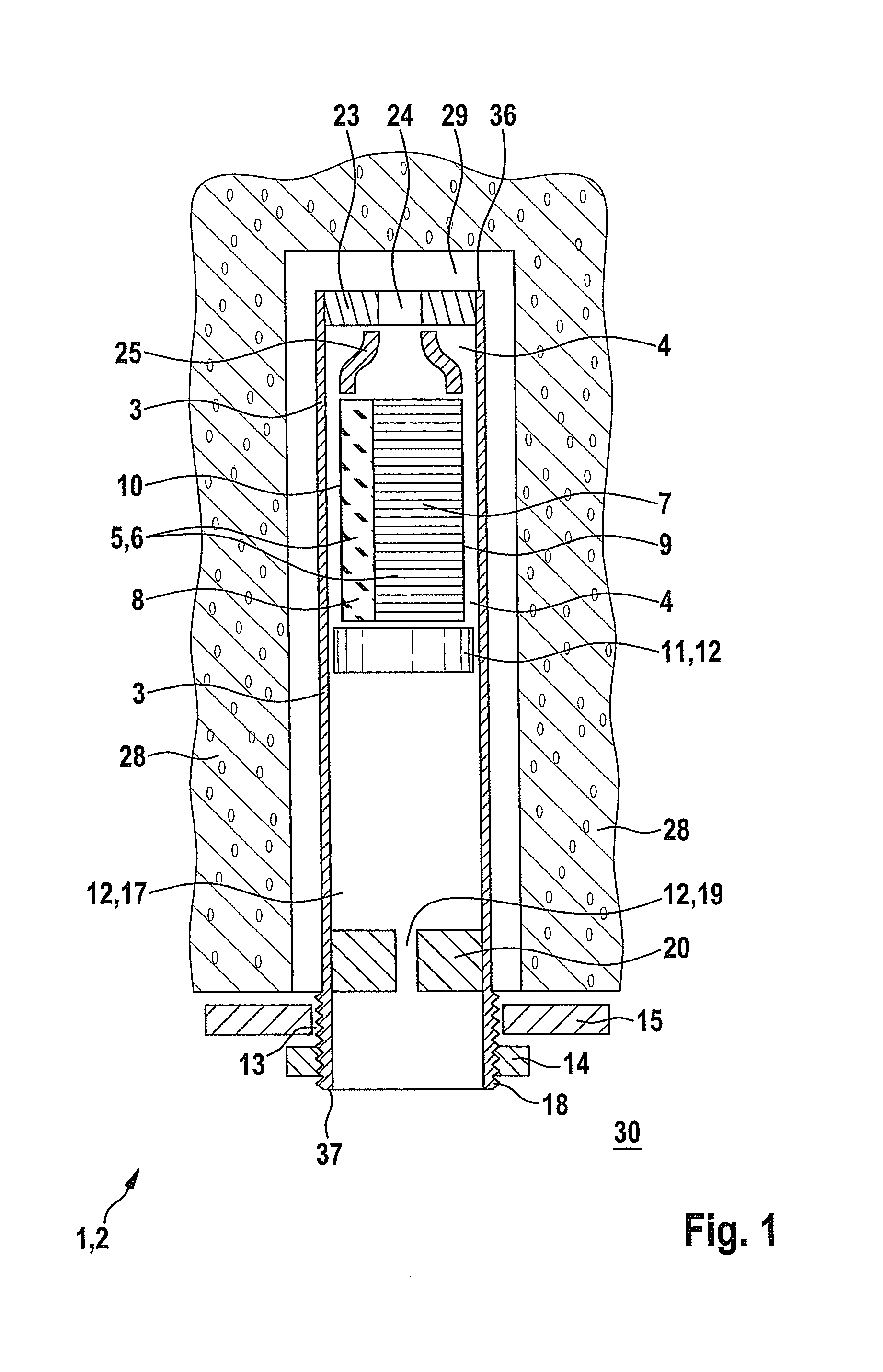
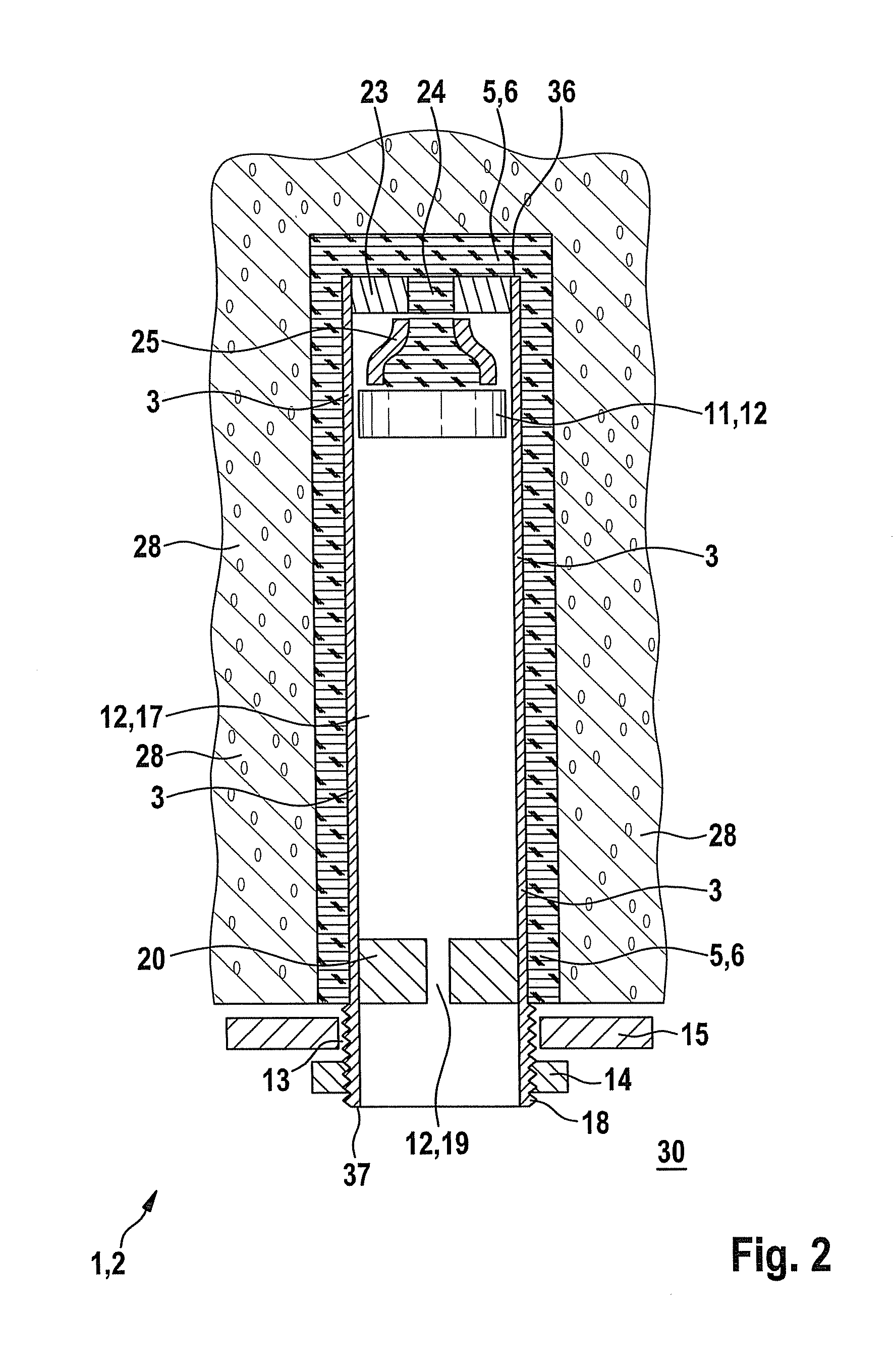
[0042]In FIGS. 4 to 8, different embodiments of the connection of the components 26, 27 are illustrated. In the first embodiment, according to FIG. 4, a plastic sheath 31 is applied by using injection molding to both the components 26 made of metal and the components 27 made of plastic. In this way, both components 26, 27 are connected to each other.

second embodiment

[0043]In the second embodiment, according to FIG. 5, fibers of the fiberglass reinforced plastic of the components 27 are applied to the outside of the components 26 made of metal. These fibers in this case are saturated with a matrix material, for example an artificial resin, and then cured. In this way, it is possible to produce a load-bearing connection to the component 26 made of metal, i.e. a steel component.

[0044]In this case, these fibers 32 are laid out as both longitudinal fibers and cross fibers.

third embodiment

[0045]In FIG. 6, the connection between the components 26, 27 is illustrated. The inner diameter of one component 26 corresponds in this case substantially to an outer diameter of another component 27. Thus the inner and outer diameters in this case substantially comprise a difference of less than 10%, 5%, 2% or 1%. In this way, the component 27 as a plastic part can be inserted coaxially into the component 26 as a steel part. By using adhesive bonding 33, both a material connection and a positive-fit connection can be produced between the components 26, 27.


PUM


Abstract

A rock bolt, particularly for use in mining, having an axial conduit, an anchor nut, and an anchor plate supported by the anchor nut for the purpose of placement on the rock, that is able to expand sufficiently and possess sufficient tensile strength, and also is able to be cut for the purpose of simplified separation of excavated pieces of the rock bolt. This problem is addressed in that the axial conduit is at least partially, and particularly entirely, made of metal and plastic, and the at least one component of the axial conduit made of metal and plastic serves to receive tensile forces.

Description

CROSS-REFERENCE TO RELATED APPLICATIONS[0001]The present application claims priority to German Patent Application DE 10 2011 004 023.4, filed Feb. 14, 2011, and entitled “Gesteinsacker” (“Rock Bolt”), which is hereby incorporated by reference in its entirety.BACKGROUND OF THE INVENTION[0002]One or more embodiments of the present invention relate to a rock bolt.[0003]In the fields of mining and tunnel construction, rock bolts are used to prevent or slow movement in the solid rock, or to secure solid rock against larger-area flaking, thereby enabling operation without danger. In this case, two functional principles are known, and are also known in partial combination. In mechanical systems, the bolt is anchored using a friction fit, wherein mechanical rock bolts generally also have an expansion sleeve and an expanding element. In the case of chemical rock bolts, an axial conduit is connected to the substrate and / or the solid rock in a material connection using a curable mortar or an a...

Claims


Application Information

Patent Timeline
Patent Type & Authority Applications(United States)
IPC IPC(8): E21D20/00E21D21/00
CPCE21D20/025E21D21/0046E21D21/0006
Inventor PODESSER, RICHARDBAYERL, MICHAEL
Owner HILTI AG
Why Eureka
Try Eureka