
High-sensitivity push-pull bridge magnetic sensor

a push-pull bridge and magnetic sensor technology, applied in the field of magnetic sensors, can solve the problems of high power consumption, complex manufacturing process of amr magnetic sensors, low sensitivity of hall magnetic sensors, etc., and achieve the effects of high sensitivity, good linearity, and small offs

Active Publication Date: 2018-02-06
MULTIDIMENSION TECH CO LTD
View PDF12 Cites 1 Cited by
  • Summary
  • Abstract
  • Description
  • Claims
  • Application Information

AI Technical Summary

Benefits of technology

[0033]Compared with the prior art, the present invention has the following beneficial effects: small offset, good linearity, high sensitivity, and low noise.

Problems solved by technology

Although Hall magnetic sensors are applicable to high-intensity magnetic fields, the Hall magnetic sensors have very low sensitivity, great power consumption and poor linearity.
Although AMR magnetic sensors are more sensitive than the Hall sensors, the AMR magnetic sensors are complex in manufacturing process and are high in power consumption.
However, the sensitivity of the existing push-pull bridge magnetic sensors is not high enough and the noise is not small enough.

Method used


Image

  • High-sensitivity push-pull bridge magnetic sensor
  • High-sensitivity push-pull bridge magnetic sensor
  • High-sensitivity push-pull bridge magnetic sensor

Examples


Embodiment Construction

[0041]The present invention will be further described below in detail in conjunction with the drawings and the embodiments.

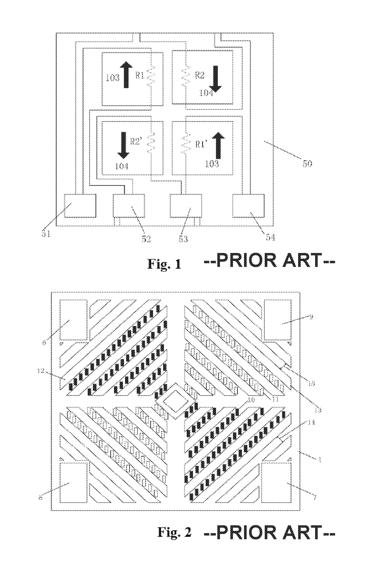
[0042]FIG. 1 is a structural schematic diagram of a common push-pull bridge magnetic sensor in the prior art. The structure of the sensor is a Wheatstone full-bridge consisting of GMR elements, magnetization directions of pinning layers of the GMR elements in adjacent bridge arms are opposite, and magnetization directions of pinning layers of the GMR elements in opposed bridge arms are the same, as shown by 103 and 104 in FIG. 1. The sensor comprises a substrate 50, R1, R1′, R2 and R2′ consisting of electrically interconnected GMR elements, pads 51-54 for input / output. The sensor adopts a double film forming process, i.e., the GMR elements which are opposite in directions of pinning layers are respectively deposited in two steps, such that the manufacturing process thereof is complex, and process annealing in the second step will influence a thin film which is d...


PUM


Abstract

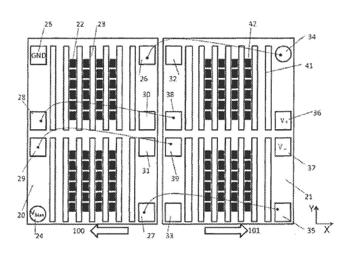
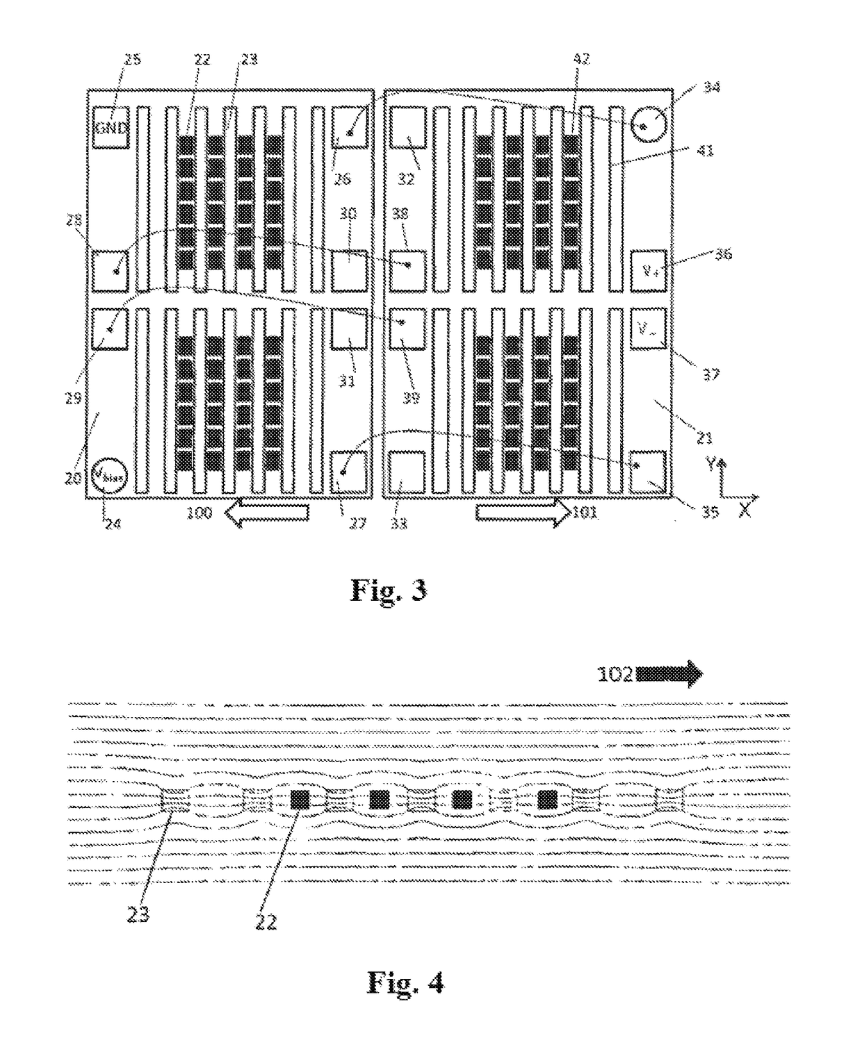
A high sensitivity push-pull bridge magnetic sensor, wherein the sensor comprises two substrates, magnetoresistive sense elements, push-arm flux concentrators, and pull-arm flux concentrators, wherein the magnetization directions of the pinning layers of the magnetoresistive sense elements on the same substrate are the same, but are opposite to the magnetization directions of the pinning layers of the magnetoresistive sense elements on the adjacent substrate, and the magnetoresistive sense elements on one substrate are electrically interconnected to form a push-arm of the bridge, and the magnetoresistive sense elements on the other substrate are electrically interconnected to form a pull-arm of the bridge. The magnetoresistive sense elements on the push-arm and pull-arm are aligned respectively in the gaps between two adjacent push-arm flux concentrators and two adjacent pull-arm flux concentrators. This sensor can be implemented as a quasi-bridge structure, a half-bridge structure, or a full-bridge structure. The sensor has the advantages of small offset, high sensitivity, excellent linearity, and low noise.

Description

PRIORITY CLAIM TO RELATED APPLICATIONS[0001]This application is a U.S. national stage application filed under 35 U.S.C. § 371 from International Application Serial No. PCT / CN2014 / 094796, which was filed 24 Dec. 2014, and published as WO2015 / 096731 on 2Jul. 2015, and which claims priority to Chinese Application No. 201310718969.8, filed 24 Dec. 2013, which applications and publication are incorporated by reference as if reproduced herein and made a part hereof in their entirety, and the benefit of priority of each of which is claimed herein.FIELD OF THE INVENTION[0002]The present invention relates to the technical field of magnetic sensors, in particular to a high-sensitivity push-pull bridge magnetic sensor.BACKGROUND OF THE INVENTION[0003]Magnetic sensors are widely applied to modern industry and electronic products to sense magnetic field intensity to measure physical parameters such as current, position and direction. In the prior art, there are many different types of sensors wh...

Claims


Application Information

Patent Timeline
Patent Type & Authority Patents(United States)
IPC IPC(8): G01R33/02G01R33/09G01R33/00
CPCG01R33/091G01R33/096G01R33/09G01R33/0011
Inventor DEAK, JAMES GEZALI, DAN
Owner MULTIDIMENSION TECH CO LTD
Learn More