Push-pull bridge-type magnetic sensor for high-intensity magnetic fields

a magnetic sensor and high-intensity technology, applied in the field of magnetosensors, can solve the problems of large power consumption, poor linearity, low sensitivity, etc., and achieve the effects of small offset, good linearity, and low power consumption

Active Publication Date: 2018-01-02
MULTIDIMENSION TECH CO LTD
View PDF12 Cites 1 Cited by
  • Summary
  • Abstract
  • Description
  • Claims
  • Application Information

AI Technical Summary

Benefits of technology

[0028]Compared with the prior art, the present invention has the following beneficial effects: low power consumption, small offsets, good linearity, wide operation range, and operation capability in high-intensity magnetic fields; Further, the sensitivity of the design can reach twice the maximum sensitivity of a single-chip reference bridge-type design.

Problems solved by technology

Although Hall magnetic sensors can work in high-intensity magnetic fields, they have disadvantages of low sensitivity, large power consumption, poor linearity and the like.
Although AMR magnetic sensors have higher sensitivity than Hall magnetic sensors, the manufacturing process thereof is complex, the power consumption is high and thus they are not suitable for high-intensity magnetic fields.
GMR magnetic sensors have higher sensitivity than Hall magnetic sensors, however, its linearity range is relatively small and thus they are not suitable for high-intensity magnetic fields, either.
However, the existing TMR magnetic sensors are still not suitable for working in high-intensity magnetic fields, and the linearity range is not wide enough.

Method used


Image

  • Push-pull bridge-type magnetic sensor for high-intensity magnetic fields
  • Push-pull bridge-type magnetic sensor for high-intensity magnetic fields
  • Push-pull bridge-type magnetic sensor for high-intensity magnetic fields

Examples


embodiments

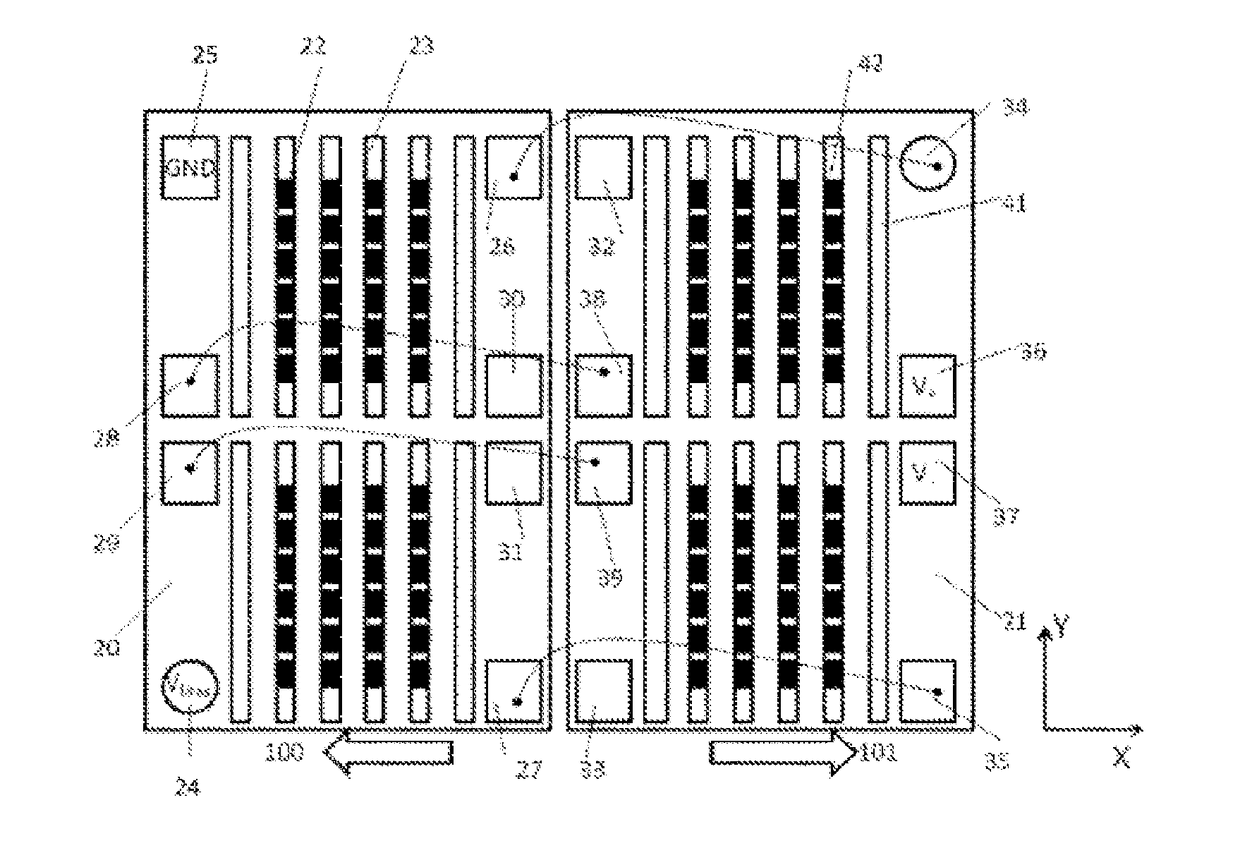
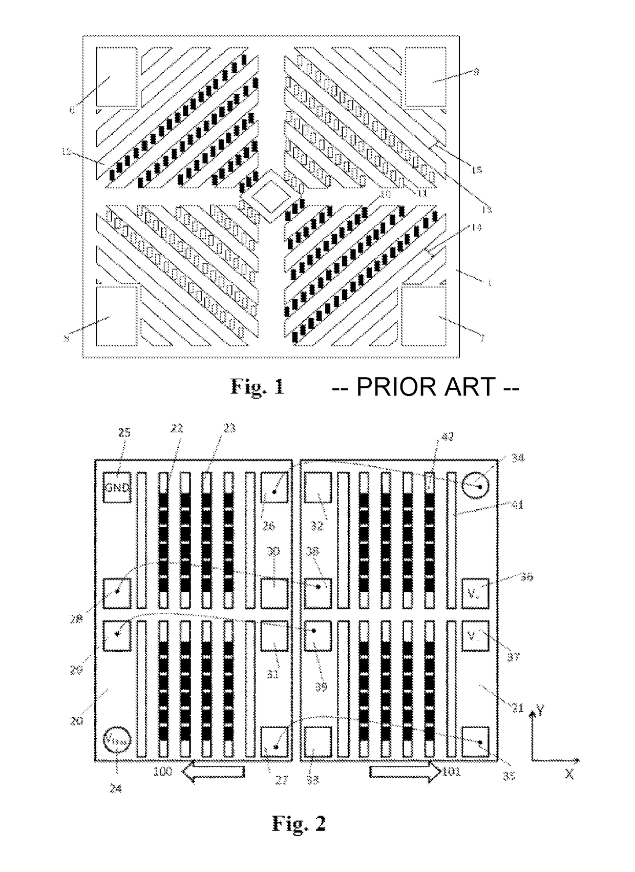
[0039]FIG. 2 is a structural schematic diagram of a push-pull bridge-type magnetic sensor in the present invention. The sensor comprises a push arm substrate 20, a pull arm substrate 21, a plurality of magnetoresistive sensing elements 22, 42, a plurality of push arm attenuators 23 and pull arm attenuators 41, and pads 24-39, wherein the magnetoresistive sensing elements 22, the push arm attenuators 23 and the pads 24-31 are deposited on the push arm substrate 20, the magnetoresistive sensing elements 42, the pull arm attenuators 41 and the pads 32-39 are deposited on the pull arm substrate 21, and the push arm substrate 20 and the pull arm substrate 21 are the same except for directions. Long axis directions of the push arm attenuators 23 and the pull arm attenuators 41 are a Y-axis direction, and short axis directions are an X-axis direction. The pads 24, 25, 36 and 37 are respectively used as a power supply terminal VBias, a ground terminal GND and voltage output terminals V+ and...


PUM


Abstract

The present invention provides a push-pull bridge-type magnetic sensor for high-intensity magnetic fields. The sensor comprises two substrates, magnetoresistive sensing elements, push arm attenuators, and pull arm attenuators. Magnetization directions of pinning layers of the magnetoresistive sensing elements located on a same substrate are parallel, and magnetization directions of pinning layers of the magnetoresistive sensing elements on different substrates are anti-parallel, wherein the magnetoresistive sensing elements on one substrate are electrically connected to one another to form push arms of a push-pull bridge, and the magnetoresistive sensing elements on the other substrate are electrically connected to one another to form pull arms of the push-pull bridge. The magnetoresistive sensing elements in the push arms and the pull arms are arranged in columns above or below the push arm attenuators and the pull arm attenuators. The sensor can be implemented in quasi-bridge, half-bridge, or full-bridge structures, and it has the following advantages: low power consumption, small offset, good linearity, wide operation range, the capability to operate in high-intensity magnetic fields, and twice the maximum sensitivity of a single-chip referenced bridge magnetic sensor.

Description

PRIORITY CLAIM TO RELATED APPLICATIONS[0001]This application is a U.S. national stage application filed under 35 U.S.C. §371 from International Application Serial No. PCT / CN2014 / 088503, which was filed 13 Oct. 2014, and published as WO2015 / 058632 on 30 Apr. 2015, and which claims priority to Chinese Application No. 201310496945.2, filed 21 Oct. 2013, which applications and publication are incorporated by reference as if reproduced herein and made a part hereof in their entirety, and the benefit of priority of each of which is claimed herein.FIELD OF THE INVENTION[0002]The present invention relates to the technical field of magnetic sensors, in particular to a push-pull bridge-type magnetic sensor for high-intensity magnetic fields.BACKGROUND OF THE INVENTION[0003]Magnetic sensors are widely used in modern industrial and electronic products to sense the magnetic field intensity to measure physical parameters such as current, position and direction. In the prior art, there are many di...

Claims


Application Information

Patent Timeline
Patent Type & Authority Patents(United States)
IPC IPC(8): G01R33/02G01R33/00G01R33/09
CPCG01R33/0011G01R33/098G01R33/093G01R33/09
Inventor DEAK, JAMES GEZA
Owner MULTIDIMENSION TECH CO LTD
Why Eureka
Try Eureka