Two-part floating electric connector

Inactive Publication Date: 2018-02-06
AMPHENOL EAST ASIA ELECTRONICS TECH SHENZHEN
View PDF11 Cites 14 Cited by
  • Summary
  • Abstract
  • Description
  • Claims
  • Application Information

AI Technical Summary

Benefits of technology

[0003]To solve the above described technical problem, the present application provides a new electric connector, which is floatable relative to th

Problems solved by technology

The electric connectors used specifically in server field must allow for a current of 50 A, which gives rise to hidden risks upon its electric leakage.

Method used


Image

  • Two-part floating electric connector
  • Two-part floating electric connector

Examples


embodiment 1

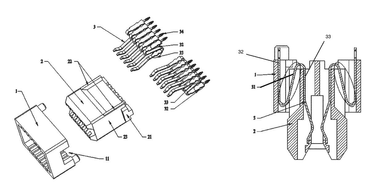
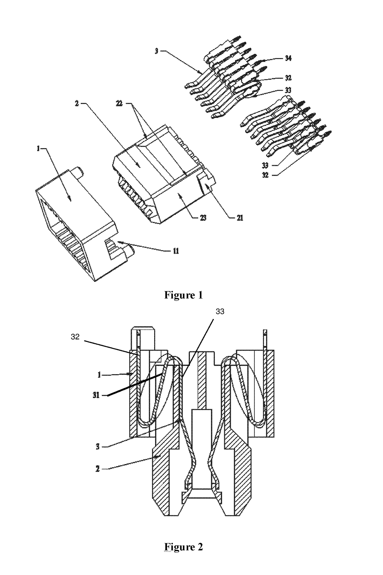
[0023]As shown in FIGS. 1 and 2, a new electric connector comprises a fastening body 1, a floating body 2 and a plurality of electric terminals 3. The fastening body 1 includes two stop grooves 11, the floating body 2 includes two stop protrusions 21, and the electric terminals 3 include resilient segments 31.

[0024]The fastening body 1 can overlap the outside of the floating body 2. The two stop protrusions 21 are respectively located on the two sides of the floating body 2, and are respectively clutched in the two stop grooves 11 when the fastening body 1 overlaps the outside of the floating body 2.

[0025]The electric terminals 3 are divided into two sets, and are plugged into the fastening body 1 and the floating body 2 at the same time when the fastening body 1 overlaps the outside of the floating body 2.

[0026]The resilient segments 31 are located at one end of the electric terminals 3 and are made by folding each electric terminal into a two layer structure.

[0027]The floating bod...


PUM


Abstract

The present application relates to the field of electric connector, particularly to an electric connector. The electric connector comprises a fastening body, a floating body and a plurality of electric terminals. The fastening body includes stop grooves, the floating body includes stop protrusions, and the electric terminals include resilient segments. The fastening body can overlap the outside of the floating body. The two stop protrusions are respectively located at the two sides of the floating body, and are respectively clutched in the two stop grooves when the fastening body 1 overlaps the outside of the floating body. The electric terminals are divided into two sets and are plugged into the fastening body and the floating body at the same time when the fastening body overlaps the outside of the floating body. The resilient segments are respectively located at one end of the electric terminals and are made by folding each electric terminal into a two layer structure.

Description

TECHNICAL FIELD[0001]The present application relates to the field of electric connector, particularly to an electric connector.BACKGROUND[0002]An electric connector is an electrical device for transferring a current. The electric connectors used specifically in server field must allow for a current of 50 A, which gives rise to hidden risks upon its electric leakage. Electric leakage likely occurs due to improper plug-in between the plug and socket of the electric connector during the usage of the electric connector.SUMMARY OF THE APPLICATION[0003]To solve the above described technical problem, the present application provides a new electric connector, which is floatable relative to the plug by optimizing its structures, provides a better plug-in and match between itself and the plug, and allows a current of 50 A to run through.[0004]To achieve the above described objective, the present application provides an electric connector comprising:[0005]a fastening body, which includes stop ...

Claims


Application Information

Patent Timeline
IPC IPC(8): H01R13/629H01R24/60H01R12/58H01R13/502H01R13/428H01R107/00
CPCH01R13/502H01R13/428H01R12/585H01R24/60H01R2107/00H01R12/7088H01R12/91
Inventor HU, HAIXI
Owner AMPHENOL EAST ASIA ELECTRONICS TECH SHENZHEN
Why Eureka
Try Eureka