

Line anti-vibration hammer capable of adjusting resonant frequencies
A technology of resonant frequency and anti-vibration hammer, which is applied in the field of anti-vibration hammer, can solve the problems of inability to achieve resonance and vibration reduction, achieve good matching, and save the weight of the device
- Summary
- Abstract
- Description
- Claims
- Application Information
AI Technical Summary
Problems solved by technology
Method used
Image

Examples
specific Embodiment approach 1
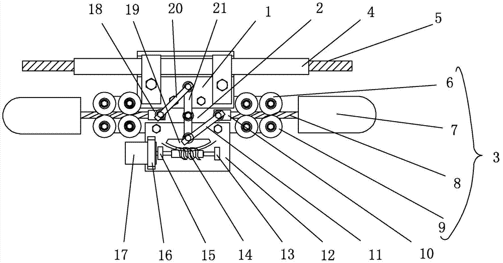
[0012] Specific implementation mode one: combine figure 1 Describe this embodiment, a line anti-vibration hammer with adjustable resonance frequency in this embodiment includes a wire clamp assembly 1 and a wire grommet 4, the wire grommet 4 is set on the wire 5, and the wire clamp assembly 1 is installed on the wire grommet 4 Above, the line anti-vibration hammer also includes an intermediate supporting plate 2, two resonance devices 3, a first connecting rod 11, a lower supporting plate 12, a first rotating member 13, a screw 14, a second rotating member 15, a pressing plate 16, a step Enter motor 17, worm gear 19, second connecting rod 20 and rotating rod 21, middle supporting plate 2 is connected with the lower end of clamp assembly 1 by screw, lower supporting plate 12 is installed on the lower end of middle supporting plate 2, and stepper motor 17 passes through The pressure plate 16 is installed on the lower supporting plate 12, the output end of the stepping motor 17 i...
specific Embodiment approach 2
[0013] Specific implementation mode two: combination figure 1 To illustrate this embodiment, the line anti-vibration hammer of this embodiment also includes a first fixed head 10 and a second fixed head 18, and the other end of the first connecting rod 11 and the other end of the second connecting rod 20 pass through the first fixed head 10 respectively. And the second fixed head 18 is rotatably connected with a resonance device 3 . Such arrangement facilitates the smooth rotation of the resonance device 3 , and also facilitates the connection of the other end of the first connecting rod 11 and the other end of the second connecting rod 20 to the first fixing head 10 and the second fixing head 18 . Other compositions and connections are the same as in the first embodiment.
specific Embodiment approach 3
[0014] Specific implementation mode three: combination figure 1 This embodiment will be described. Both the first rotating member 13 and the second rotating member 15 in this embodiment are bearings. Such arrangement facilitates weight reduction and flexible rotation. Other compositions and connections are the same as those in Embodiment 1 or Embodiment 2.
PUM
 Abstract
Description
Claims
Application Information