7/16 negative connector

A connector and female technology, which is applied in the field of 7/16 female connectors, can solve problems such as low work efficiency, large operating space, and design difficulties, and achieve the effects of reducing device weight, improving work efficiency, and reducing thickness

Inactive Publication Date: 2010-02-24
AMPHENOL CNT XIAN TECH
View PDF0 Cites 0 Cited by
  • Summary
  • Abstract
  • Description
  • Claims
  • Application Information

AI Technical Summary

Problems solved by technology

There are two ways to connect the outer conductors of the female and male connectors: threaded connection and in-line connection. The threaded connection has high reliability, strong shock resistance, and wide operating frequency range, but it takes a long time to install and disassemble, low work efficiency, and requires a large amount of operation. Space This is not conducive to the miniaturization of equipment. Usually, large and medium-sized connectors mostly use threaded connections, of which 7/16 are large connectors. Previous projects mainly used threaded connections.
[0003] The 7/16 female connector is often fixed together with the equipment and can be called a 7/16 socket. The outer conductor of the 7/16 socket is the inner diameter of the shell is 16 mm, the outer diameter is 29 mm, and the wall thickness is 13 mm. , the wall thickness must be heavy, which is not conducive to use and transportation. For this wall thickness and weight, the shell is usually designed as two layers, in which the inner layer is used as the outer conductor of the coaxial structure, and the outer layer is the threaded structure used to connect with the male connector. A useless tubular gap is formed between the inner and outer layers. The double-layer shell is formed with one more piece of material, that is, the heels of the two-layer

Method used


Image

  • 7/16 negative connector
  • 7/16 negative connector
  • 7/16 negative connector

Examples


Example Embodiment

[0024] The structure and working principle of the present invention will be described in detail below in conjunction with the accompanying drawings.

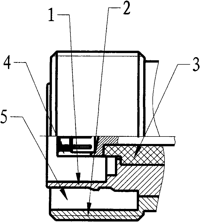
[0025] see figure 1 , a 7 / 16 female connector, including a shell 2, the shell 2 is provided with an outer conductor 1, the inner cavity of the outer conductor 1 is provided with an insulator 3, and the insulator 3 is provided with an inner conductor 4. There is a gap 5 between the outer conductor 1 and the shell 2, and the width of the gap 5 is 3.3-3.4 mm.

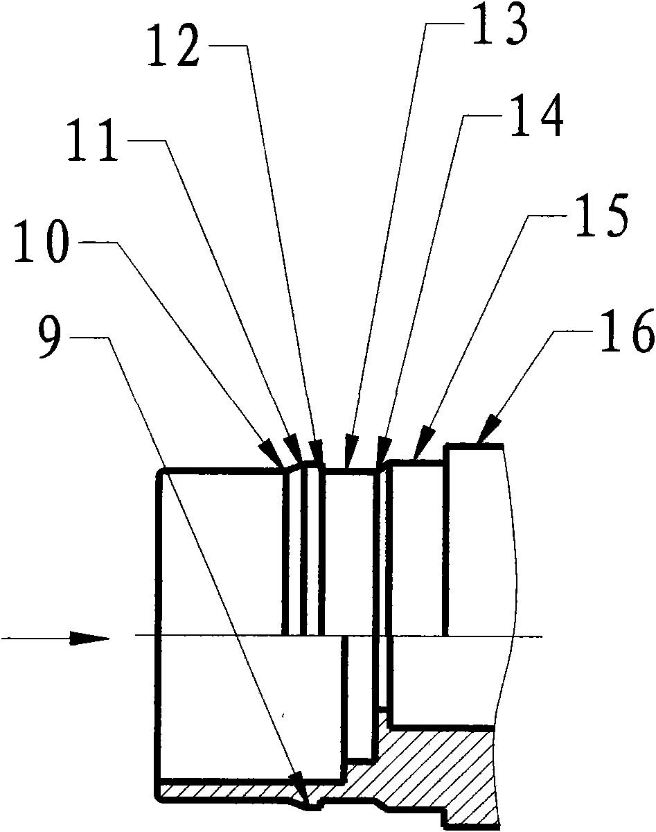
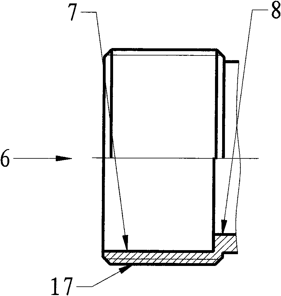
[0026] see figure 2 , 3 , 4, the outer circle of the outer conductor 1 is provided with a bump 9, the length of the bump 9 is greater than or equal to 2 millimeters; the mouth of the bump 9 at the outer end of the outer conductor 1 intersects with the outer circle of the outer conductor 1, and the intersection forms a Groove 10, the groove 10 intersects with the top of the bump 9 at a horizontal angle of 22 degrees to form a circle of intersecting ribs 11, and the inters...


PUM

PropertyMeasurementUnit
Lengthaaaaaaaaaa

Abstract

A 7/16 negative connector comprises a shell 2, the shell 2 is internally provided with an outer conductor 1, an insulator 3 is arranged in the inner cavity of the outer conductor 1, an inner conductor4 is arranged in the insulator 3, a lug 9 is arranged at the excircle of the outer conductor 1, the lug 9 can expand out the inner diameter of a clamp ring 18 to let the clamp ring 18 enter into a clamp ring groove 20 of a positive connector, when the negative connector and the positive connector are mutually inserted and an annular face 12 of the outer conductor 1 enters into a small head 19 ofthe clamp ring 18, the inner diameter of the small head is contracted, and the annular face 12 is immediately clamped at the end face of the small head 19 to ensure that the two connectors are clampedtogether and can not automatically separate; when needing separating, the slant face of a clamp ring sleeve 21 is pulled upwards to expand out the clamp ring 18 and let the clamp ring 18 enter into the clamp ring groove 20, the end face of the small head 19 departs from the annular face 12 of the outer conductor 1 to be drawn out of the positive connector. The invention has the characteristics ofsimple structure, easy processing, reliable connection and good performance.

Description

technical field [0001] The invention relates to a connector, in particular to a 7 / 16 female connector. Background technique [0002] RF coaxial connector is one of the most widely used devices in communication systems. Its function is to connect coaxial systems such as system and system, equipment and equipment, components and components, so that the signal can be continuously conducted without distortion and attenuation. With the rapid development of the communication industry, new requirements are constantly put forward for the types and functions of RF coaxial connectors, requiring more convenient use, more suitable structure, lower cost, better performance, etc., to adapt to the rapid development of the communication industry. The basic structure of the coaxial connector is composed of the inner conductor of the input signal, the outer conductor of the output signal and the insulating medium layer separating the two conductors. Coaxial connectors are used in pairs, wher...

Claims


Application Information

Patent Timeline
IPC IPC(8): H01R24/02H01R13/62H01R24/38
Inventor 胡波
Owner AMPHENOL CNT XIAN TECH
Why Eureka
Try Eureka