Optoelectronic integrated device and manufacturing method thereof

A technology of integrated devices and optoelectronic devices, which is applied in the field of semiconductors, can solve problems such as complex manufacturing processes, and achieve the effects of suppressing optical resonance problems, reducing thickness, and reducing attenuation

Pending Publication Date: 2020-07-28
SILERGY SEMICON TECH (HANGZHOU) CO LTD
View PDF0 Cites 2 Cited by
  • Summary
  • Abstract
  • Description
  • Claims
  • Application Information

AI Technical Summary

Problems solved by technology

However, its production p

Method used


Image

  • Optoelectronic integrated device and manufacturing method thereof
  • Optoelectronic integrated device and manufacturing method thereof
  • Optoelectronic integrated device and manufacturing method thereof

Examples


Embodiment Construction

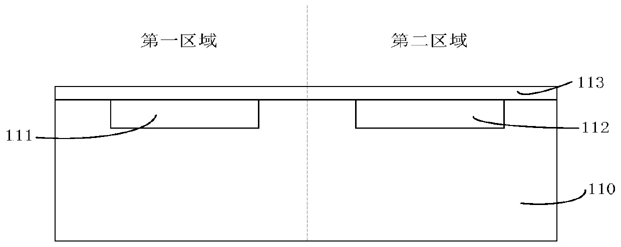
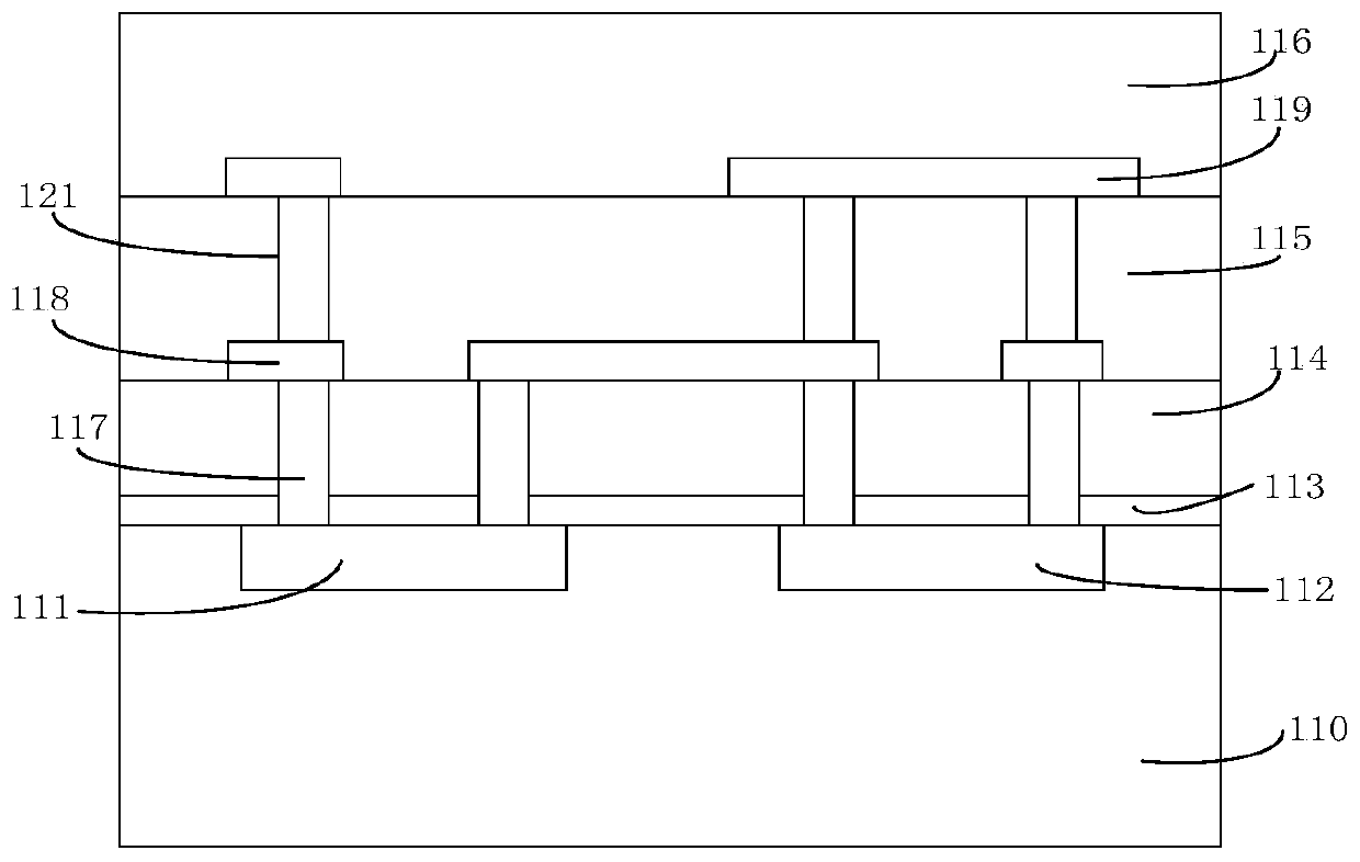
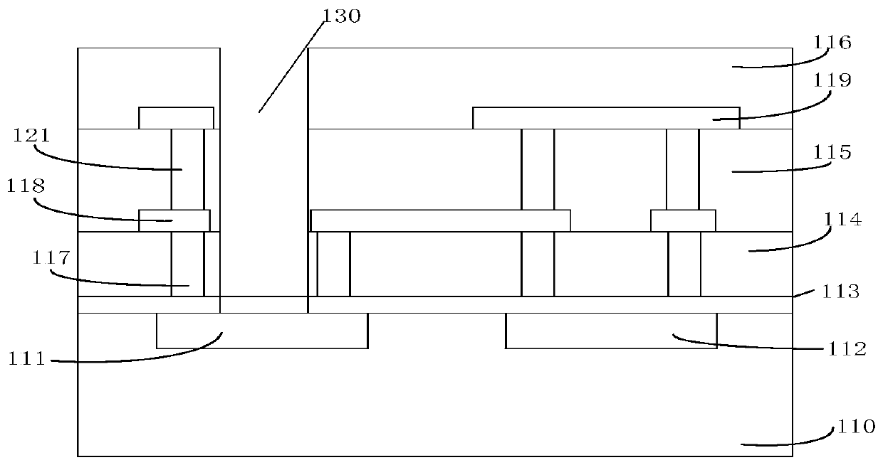
[0040] Hereinafter, the present invention will be described in more detail with reference to the accompanying drawings. In the various figures, identical elements are indicated with similar reference numerals. For the sake of clarity, various parts in the drawings have not been drawn to scale. Also, some well-known parts may not be shown. For the sake of simplicity, the semiconductor structure obtained after several steps can be described in one figure.

[0041] It should be understood that when describing the structure of a device, when a layer or a region is referred to as being "on" or "over" another layer or another region, it may mean being directly on another layer or another region, or Other layers or regions are also included between it and another layer or another region. And, if the device is turned over, the layer, one region, will be "below" or "beneath" the other layer, another region.

[0042] If it is to describe the situation directly on another layer or an...


PUM

PropertyMeasurementUnit
Thicknessaaaaaaaaaa

Abstract

The invention discloses a photoelectric integrated device and a manufacturing method thereof. The method comprises the steps: providing a semiconductor substrate at least comprising a photoelectric device; forming a first dielectric layer on the first surface of the semiconductor substrate; forming an insulating layer on the first dielectric layer; forming a first opening in the insulating layer to expose the first dielectric layer above the photoelectric device region; and forming a second dielectric layer on the exposed first dielectric layer, wherein the first dielectric layer and the second dielectric layer are anti-reflection layers. According to the photoelectric integrated device provided by the invention, light can enter the photoelectric device only through the anti-reflection layer, so that excellent optical characteristics be acquired, and the manufacturing cost is reduced.

Description

technical field [0001] The invention relates to the technical field of semiconductors, and more specifically, to an optoelectronic integrated device and a manufacturing method thereof. Background technique [0002] Optoelectronic integrated circuits, such as image sensors, are optoelectronic components used to acquire light signals and convert them into analog or digital electrical signals. These optoelectronic integrated circuits are widely used in consumer electronics, medical electronics, and portable devices, such as digital cameras and smartphone etc. The principle of the complementary metal oxide semiconductor (CMOS) image sensor is to pass the light collected by the microlens through a color filter, a protective layer, an inner metal dielectric layer (IMD), an inner dielectric layer (ILD) After that, it will be finally received by the n-type or p-type photosensor unit, and the photosensor unit will convert the number of photons into an electronic signal. In addition...

Claims


Application Information

Patent Timeline
IPC IPC(8): H01L27/146
CPCH01L27/14685H01L27/1462H01L27/14625H01L31/02161H01L31/02005H01L31/02327H01L31/101H01L31/186
Inventor 吕政何惠森黄贤国
Owner SILERGY SEMICON TECH (HANGZHOU) CO LTD
Why Eureka
Try Eureka