
Recording apparatus with movable feed roller

a technology of feed roller and recording apparatus, which is applied in the direction of transportation and packaging, thin material processing, and article separation, etc., can solve the problems of inability to secure the free adjustment, and achieve the effect of reducing the configuration of the apparatus

Active Publication Date: 2018-02-13
SEIKO EPSON CORP
View PDF13 Cites 0 Cited by
  • Summary
  • Abstract
  • Description
  • Claims
  • Application Information

AI Technical Summary

Benefits of technology

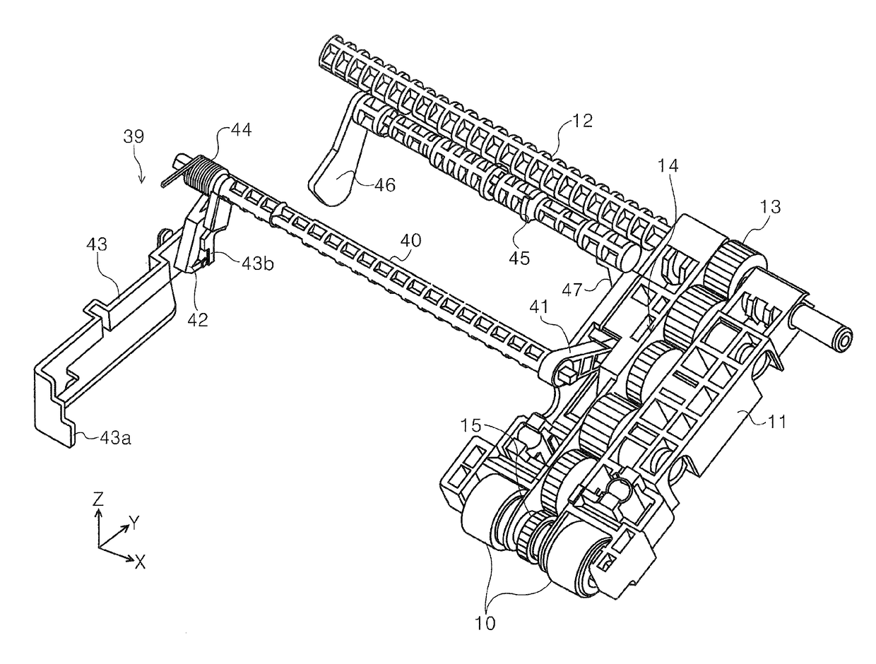
The invention provides a recording apparatus that takes into account usability when inserting and removing a tray which stores paper. A cam shaft is provided in the tray storage portion with first and second engaging portions that engage with the tray and the roller support member which supports the feed roller. The roller support member changes posture due to the tray causing the cam shaft to rotate, making it easy to adjust the operational force when changing the posture of the roller support member. This results in a greater degree of freedom in securing the engagement position between the first and second engaging portions, and further enhances usability. In a configuration with multiple trays, the same benefits can be obtained. Additionally, both bottom and top level trays are configured to cause the cam shaft to rotate, simplifying the apparatus configuration and reducing costs.

Problems solved by technology

It is possible to adjust the operational force when lifting and lowering the paper feed unit (the arm) using the paper feed cassette in the configuration described in JP-A-2006-273565 by changing the engagement position between the paper feed cassette and the paper feed unit (the arm); however, since the paper feed cassette in the configuration described in JP-A-2006-273565 is configured to directly push the paper feed unit (the arm) upward, there is a problem in that freedom in adjustment may not be secured due to space concerns.

Method used


Image

  • Recording apparatus with movable feed roller
  • Recording apparatus with movable feed roller
  • Recording apparatus with movable feed roller

Examples


second embodiment

5. Second Embodiment

[0137]Hereinafter, description will be given of the second embodiment of the invention with reference to FIG. 20 onward.

[0138]The second embodiment differs from the first embodiment in that the cam shaft 45 of the first embodiment described above is caused to rock by the bottom level side tray 50 in addition to the top level side tray 60. In the second embodiment, the holding unit 39, which is described with reference to the first embodiment, is not provided.

[0139]In FIG. 20, sign 145 is a cam shaft corresponding to the cam shaft 45 of the first embodiment. Sign 146 is a cam follower portion corresponding to the cam follower portion 46 of the first embodiment. Sign 147 is a cam follower portion corresponding to the cam portion 47 of the first embodiment. The functions of the cam shaft 145, the cam follower portion 146, and the cam portion 147 are the same as in the corresponding configuration already described in the first embodiment.

[0140]The second embodiment d...


PUM


Abstract

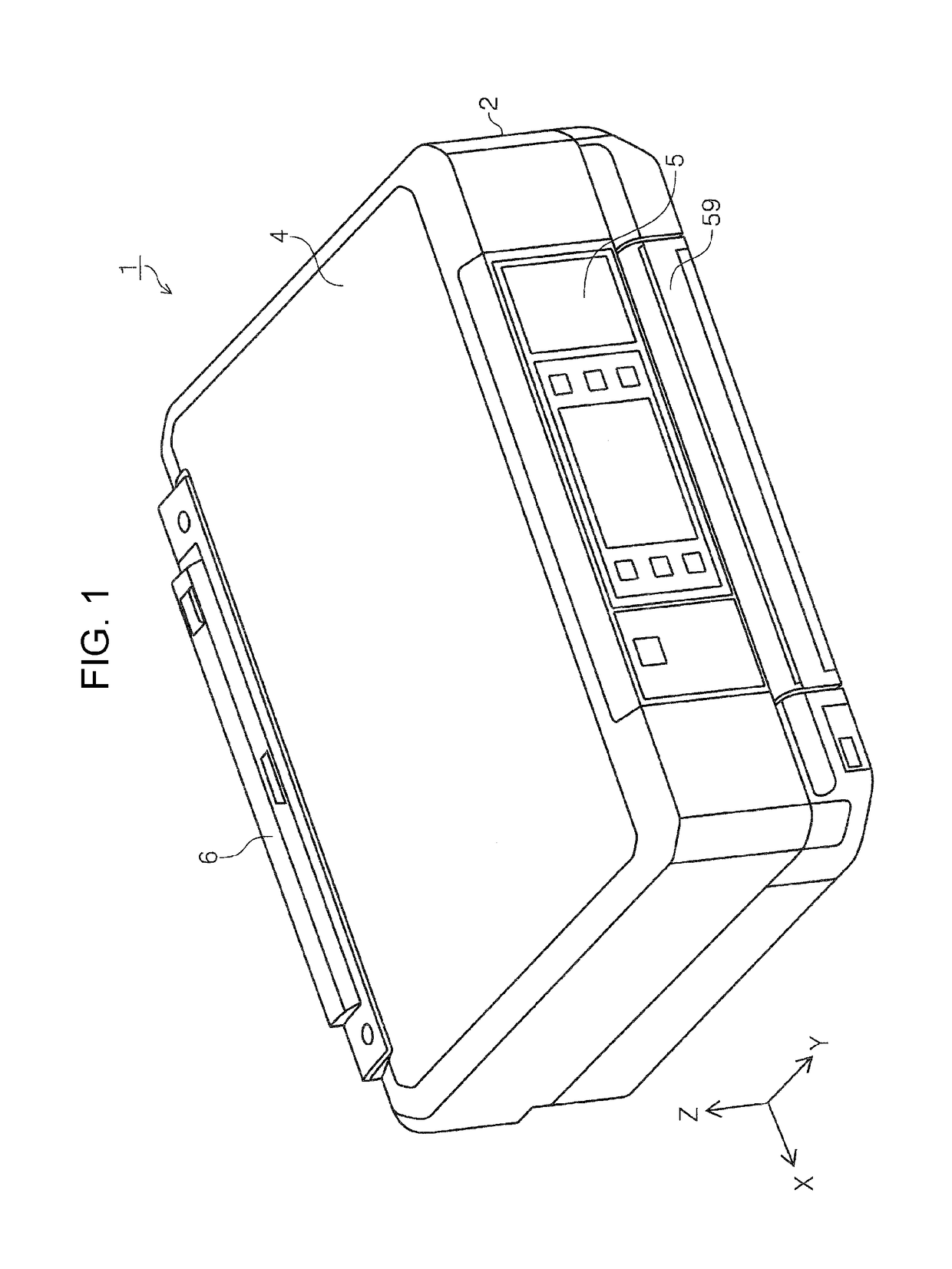
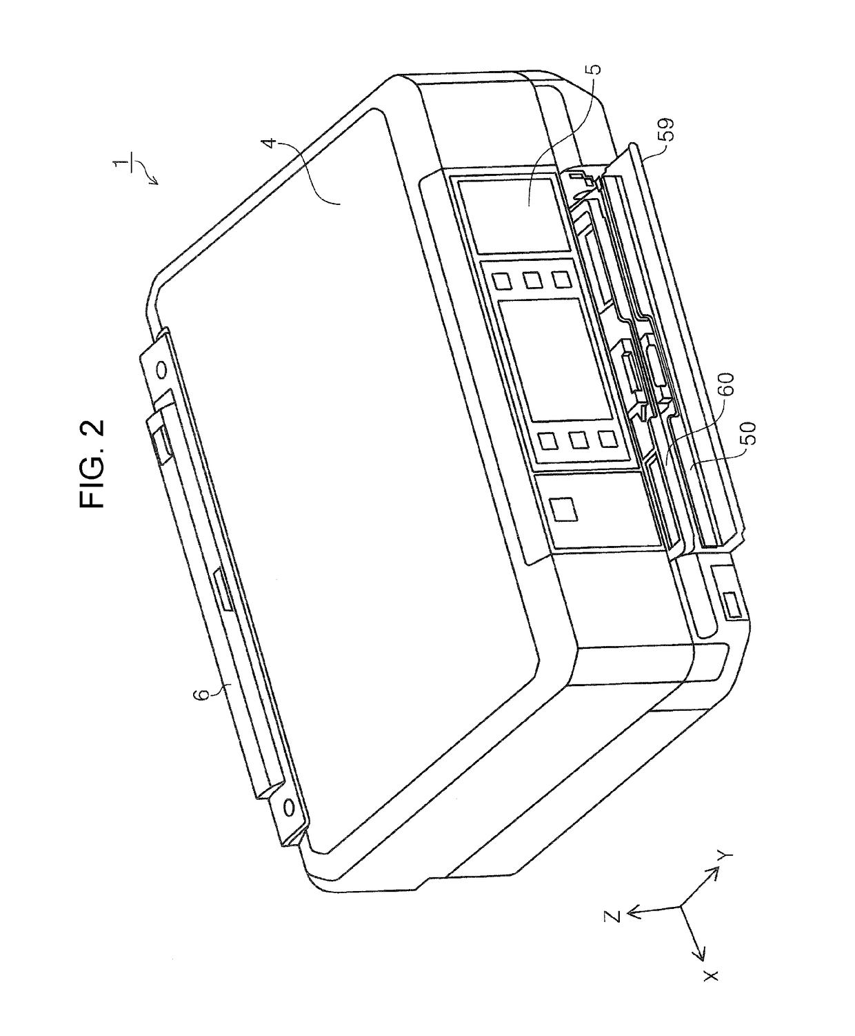
A recording apparatus includes a recording unit which performs recording on a recording medium, a tray which stores the recording medium, a tray storage portion which stores the tray, a feed roller which feeds the recording medium out from the tray, and a roller support member which supports the feed roller and causes the feed roller to be lifted and lowered in relation to the tray by changing posture, in which a cam shaft capable of rotating is provided in the tray storage portion, in which the cam shaft is provided with a first engaging portion which engages with the tray and a second engaging portion which engages with the roller support member, and in which the roller support member is configured to change posture due to the tray causing the cam shaft to rotate.

Description

BACKGROUND[0001]1. Technical Field[0002]The present invention relates to a recording apparatus provided with a tray which stores a recording medium, a feed roller which feeds the recording medium from the tray, and a roller support member which supports the feed roller and lifts and lowers the feed roller in relation to the tray.[0003]2. Related Art[0004]In the recording apparatus which is represented by a facsimile, a printer, or the like, a detachable paper feed cassette in relation to the apparatus main body is widely used in the related art. There are various names, such as “cassette” and “tray”, for a detachable paper storage implement which stores paper in the recording apparatus, and in the present specification, either term will be used according to the situation.[0005]A configuration is well known in which a paper feed roller is provided above the paper feed cassette, the paper feed roller is supported by an arm (a support member), and the paper feed roller is lifted and lo...

Claims


Application Information

Patent Timeline
Patent Type & Authority Patents(United States)
IPC IPC(8): B65H1/04B65H1/26B65H3/06B65H3/44B65H7/18
CPCB65H7/18B65H3/44B65H3/0684B65H3/0669B65H1/26B65H1/04B65H2404/1531B65H2405/114B65H2405/332B65H2511/20B65H2511/214B65H2801/12B65H2801/39B65H2403/513B65H2220/01B65H2220/11B65H2220/08
Inventor OKI, NARIHIROOTSUKA, KAZUO
Owner SEIKO EPSON CORP
Learn More