
Marine propulsion device

a propulsion device and a technology for marine ships, applied in marine propulsion, vessel construction, steering initiation, etc., can solve the problems of difficult recognition for users, difficult for users to smoothly perform the operation of switching the rotation region of the accelerator grip, etc., to achieve smooth operation of switching the rotation region and significant reduction or prevention of complication of operation

Inactive Publication Date: 2018-02-20
YAMAHA MOTOR CO LTD
View PDF15 Cites 4 Cited by
  • Summary
  • Abstract
  • Description
  • Claims
  • Application Information

AI Technical Summary

Benefits of technology

The present invention aims to solve the issue of difficulty in switching the rotation region of an accelerator grip on a marine propulsion device. The invention simplifies the process, allowing the user to smoothly switch the rotation region and recognize the switch has occurred. This provides a better user experience and reduces the likelihood of complications during operation.

Problems solved by technology

Therefore, it is difficult for the user to recognize that the accelerator grip has been switched from the rotatable state in one of the forward movement rotation region and the reverse movement rotation region to the rotatable state in the other of the forward movement rotation region and the reverse movement rotation region.
Thus, although the user recognizes that the rotation region of the accelerator grip is switched, an operation of switching the accelerator grip from the rotatable state in one of the forward movement rotation region and the reverse movement rotation region to the rotatable state in the other of the forward movement rotation region and the reverse movement rotation region is complicated, and it is difficult for the user to smoothly perform the operation of switching the rotation region of the accelerator grip.

Method used


Image

  • Marine propulsion device
  • Marine propulsion device
  • Marine propulsion device

Examples


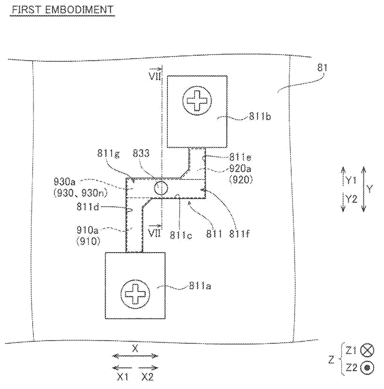
first embodiment

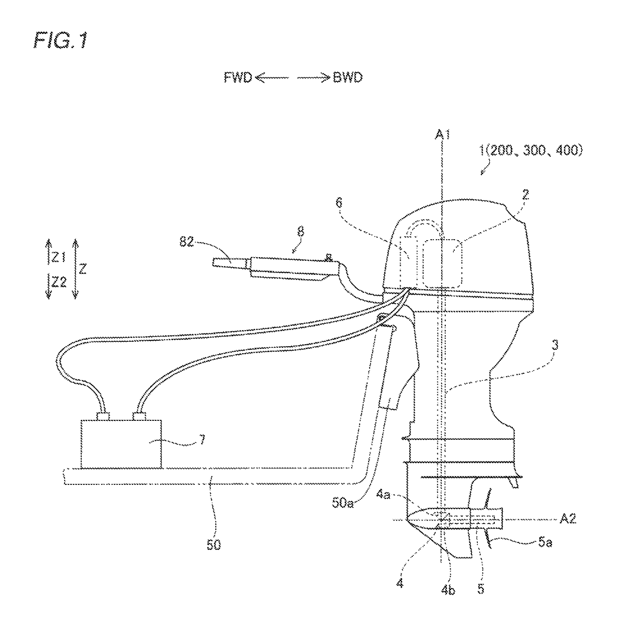
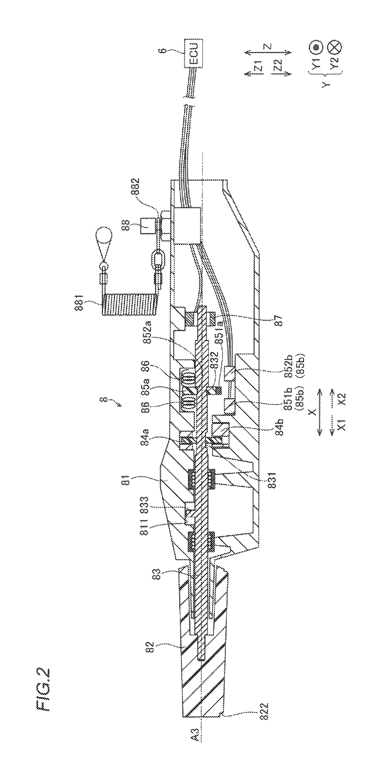
[0043]The structure of a marine propulsion device 1 according to a first embodiment of the present invention is now described with reference to FIGS. 1 to 9. In the figure, arrow FWD represents the forward movement direction of a boat body, and arrow BWD represents the reverse movement direction of the boat body.

[0044]As shown in FIG. 1, the marine propulsion device 1 includes a power source 2, a drive shaft 3, a gear portion 4, a propeller shaft 5, and an ECU (engine control unit) 6. Electric power is supplied from a battery 7 arranged in a boat body 50 to the power source 2 and the ECU 6. The marine propulsion device 1 also includes a steering handle 8. The marine propulsion device 1 is mounted on the boat body 50 through a bracket 50a.

[0045]The power source 2 includes a normally and reversely rotatable electric motor.

[0046]An upper end of the drive shaft 3 is connected to the power source 2. A lower end of the drive shaft 3 is mounted with a pinion gear 4a described later. The d...

second embodiment

[0082]The structure of a marine propulsion device 200 according to a second embodiment of the present invention is now described with reference to FIGS. 10 and 11.

[0083]In the second embodiment, the marine propulsion device 200 in which a forward movement rotation region 910 and a reverse movement rotation region 920 overlap each other, as viewed in the extensional direction of a rotation axis A3 is described, unlike the first embodiment in which the forward movement rotation region910 and the reverse movement rotation region 920 do not overlap each other, as viewed in the extensional direction of the rotation axis A3. Portions of the marine propulsion device 200 similar to those of the marine propulsion device 1 according to the aforementioned first embodiment are denoted by the same reference numerals, to omit the description.

[0084]As shown in FIG. 10, in the marine propulsion device 200 according to the second embodiment, a second engaging portion 891a is substantially U-shaped. ...

third embodiment

[0091]The structure of a marine propulsion device 300 according to a third embodiment of the present invention is now described with reference to FIGS. 12 and 13.

[0092]In the third embodiment, the marine propulsion device 300 in which a forward movement rotation region 910 and a reverse movement rotation region 920 are provided at the same positions in the extensional direction of a rotation axis A3 is described, unlike the first embodiment in which the forward movement rotation region 910 and the reverse movement rotation region 920 are provided at the positions different from each other in the extensional direction of the rotation axis A3. Portions of the marine propulsion device 300 similar to those of the marine propulsion device 1 according to the aforementioned first embodiment are denoted by the same reference numerals, to omit the description.

[0093]As shown in FIG. 12, in the marine propulsion device 300 according to the third embodiment, an axis guide portion 891g of a seco...


PUM


Abstract

A marine propulsion device includes a power source, a steering handle, and an accelerator grip that moves with respect to the steering handle. A movement region of the accelerator grip includes a forward movement rotation region, a reverse movement rotation region and an axis movement region. In the forward movement rotation region, the accelerator grip is operated to rotate so as to obtain a drive force in a forward movement direction. In the reverse movement rotation region the accelerator grip is operated to rotate so as to obtain a drive force in a reverse movement direction. The axis movement region is provided between the forward movement rotation region and the reverse movement rotation region. In the axis movement region, the accelerator grip is moved in the extensional direction of a rotation axis.

Description

CROSS-REFERENCE TO RELATED APPLICATION[0001]The priority application number JP2014-199929, Marine Propulsion Device, Sep. 30, 2014, Takayoshi Suzuki, Noriyoshi Hiraoka, Akihiro Onoue, Atsushi Kumita, and Yoshiaki Tasaka, upon which this patent application is based is hereby incorporated by reference.BACKGROUND OF THE INVENTION[0002]Field of the Invention[0003]The present invention relates to a marine propulsion device, and more particularly, it relates to a marine propulsion device including an accelerator grip.[0004]Description of the Background Art[0005]A marine propulsion device including an accelerator grip is known in general. Such a marine propulsion device is disclosed in Japanese Patent Laying-Open No. 2014-046745, for example.[0006]In general, a marine propulsion device is provided with an accelerator grip to adjust drive force in a forward movement direction or in a reverse movement direction generated from a power source. When finely adjusting forward / reverse movement of ...

Claims


Application Information

Patent Timeline
Patent Type & Authority Patents(United States)
IPC IPC(8): B63H21/21B63H21/22B63H20/20B60W10/04B63H20/12B63H25/02
CPCB63H20/20B63H20/12B63H2025/024
Inventor SUZUKI, TAKAYOSHIHIRAOKA, NORIYOSHIONOUE, AKIHIROKUMITA, ATSUSHITASAKA, YOSHIAKI
Owner YAMAHA MOTOR CO LTD
Learn More