Coilable shade

a shade and coil technology, applied in the field of coil shade, can solve the problems of poor use convenience, inability to retain any desired length of conventional shade device, and only provide a fully extended state or fully coiled state, and achieve the effects of excellent use convenience, excellent utility, and simple operation

Inactive Publication Date: 2018-02-20
CHENG LI MING
View PDF11 Cites 3 Cited by
  • Summary
  • Abstract
  • Description
  • Claims
  • Application Information

AI Technical Summary

Benefits of technology

[0006]The shade of the coilable shade according to the present disclosure can be controlled to be retained in any desired extended length through simple operation while providing excellent use convenience as well as fulfilling different shielding effects. Thus, the coilable shade has excellent utility.
[0007]The shade holding device can further include two lateral boards opposite to each other and two rods. The two pivotal portions are disposed on two mutually facing sides respectively of the two lateral boards. Two ends of each of the two rods are respectively fixed to the two lateral boards. The elastic enveloping strap includes a first end fixed between the two ends of one of the two rods and a second end having a hook detachably coupled between the two ends of another of the two rods. The structure is simple and is easy to manufacture and assemble, reducing the manufacturing costs and increasing assembling convenience.
[0008]The two rods are more adjacent to the head end of the shade than the two pivotal portions are to the head end of the shade. Thus, the portion of the shade coiled around the shaft can be more securely received in the shade holding device.
[0009]Furthermore, the coilable shade can further include an elastic element. The elastic element includes a first end mounted in an interior of the shaft and a second end coupled to one of the two pivotal portions. This structure increases operational convenience while coiling the shade.

Problems solved by technology

However, the conventional shade device can only provide a fully extended state or a fully coiled state.
Namely, the conventional shade device cannot be retained in any desired length, providing poor use convenience.

Method used


Image

  • Coilable shade
  • Coilable shade
  • Coilable shade

Examples


Embodiment Construction

[0015]The present disclosure will become clearer in light of the following detailed description of illustrative embodiments of this disclosure described in connection with the drawings.

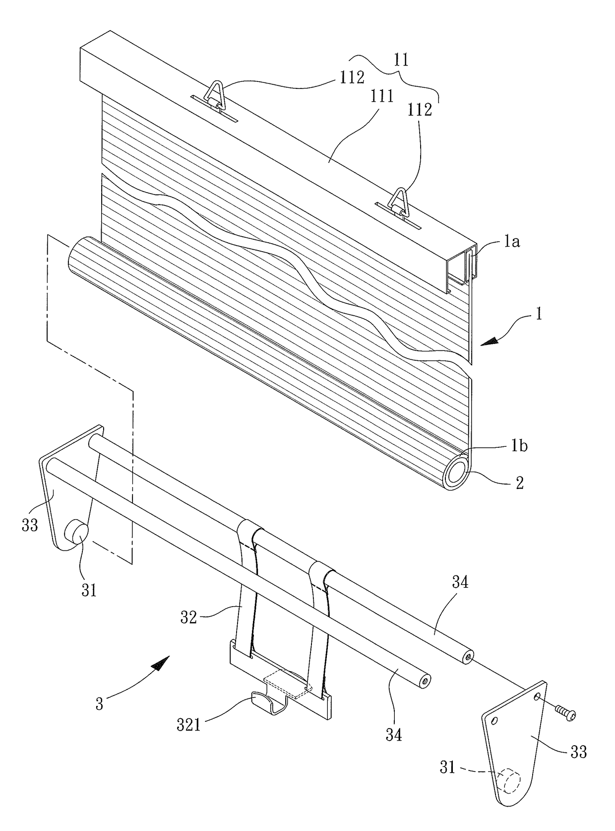
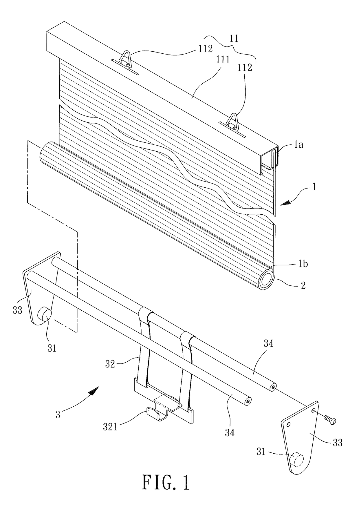
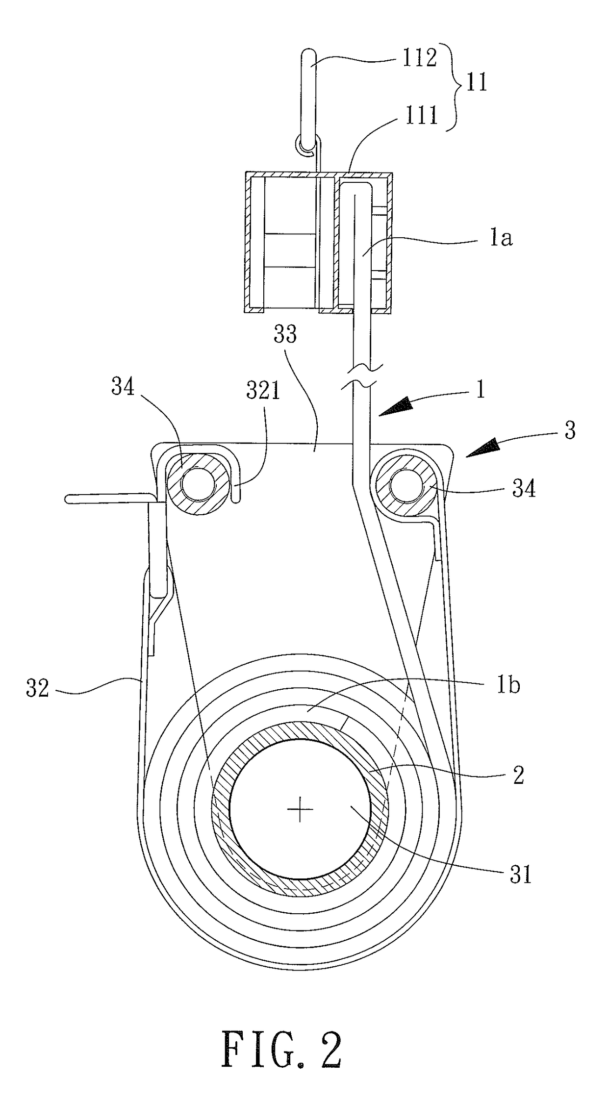
[0016]With reference to FIG. 1, a coilable shade of a first embodiment according to the present disclosure includes a shade 1, a shaft 2 and a shade holding device 3. The shaft 2 is fixed to the shade 1 and is pivotably connected to the shade holding device 3.

[0017]The shade 1 can be of any desired type, such as a piece of wood or constructed by a plurality of wood pieces, or a piece of cloth. The shade 1 includes a head end 1a and a tail end 1b. The head end 1a includes a hanger portion 11 for hanging above an opening (for a door or a window) by hooks, such that the opening can be shielded when the shade 1 is extended. In this embodiment, the hanger portion 11 includes a fixing rod 111 and a plurality of hangers 112. The head end 1a of the shade 1 can be fixed to the fixing rod 111. The hangers 112 a...


PUM


Abstract

A coilable shade includes a shade having a head end and a tail end. The head end includes a hanger portion. A shaft is fixed to the tail end of the shade. A shade holding device includes two pivotal portions opposite to each other. The shaft is coupled to the two pivotal portions. A portion of the shade coiled around the shaft is received in the shade holding device and is held by an elastic enveloping strap. The disadvantage of failure in retaining in a desired length in the conventional shade device that can only provide a fully extended state or a fully coiled state is, thus, solved.

Description

BACKGROUND OF THE INVENTION1. Field of the Invention[0001]The present disclosure relates to a coilable shade and, more particularly, to a coilable shade that can be coiled upward.2. Description of the Related Art[0002]A type of conventional shade device includes a shade having upper and lower ends respectively fixed to upper and lower rods. A plurality of hangers is fixed to the upper rod for hanging above an opening (for a door or a window) by hooks. The shade can be extended to shield the opening. When it is desired to reveal the opening, the lower rod can be moved upward toward the upper rod to coil the shade, and a strap is used to tie the lower rod.[0003]However, the conventional shade device can only provide a fully extended state or a fully coiled state. Namely, the conventional shade device cannot be retained in any desired length, providing poor use convenience. Improvement is, thus, required.SUMMARY OF THE INVENTION[0004]An objective of the present disclosure is to provide...

Claims


Application Information

Patent Timeline
Patent Type & Authority Patents(United States)
IPC IPC(8): E06B9/24E06B9/66E06B9/64E06B9/80E06B9/44E06B9/42
CPCE06B9/80E06B9/42E06B9/44E06B9/64E06B9/66E06B9/50
Inventor CHENG, LI-MING
Owner CHENG LI MING
Why Eureka
Try Eureka