

Power module with low stray inductance
a power module and low stray inductance technology, applied in the direction of semiconductor devices, semiconductor/solid-state device details, electrical apparatus, etc., can solve the problems of increasing the switching loss, reducing the controllability of semiconductor switches, and emi emissions, so as to facilitate the provision of contact areas and improve electrical balancing
- Summary
- Abstract
- Description
- Claims
- Application Information
AI Technical Summary
Benefits of technology
Problems solved by technology
Method used
Image

Examples
Embodiment Construction
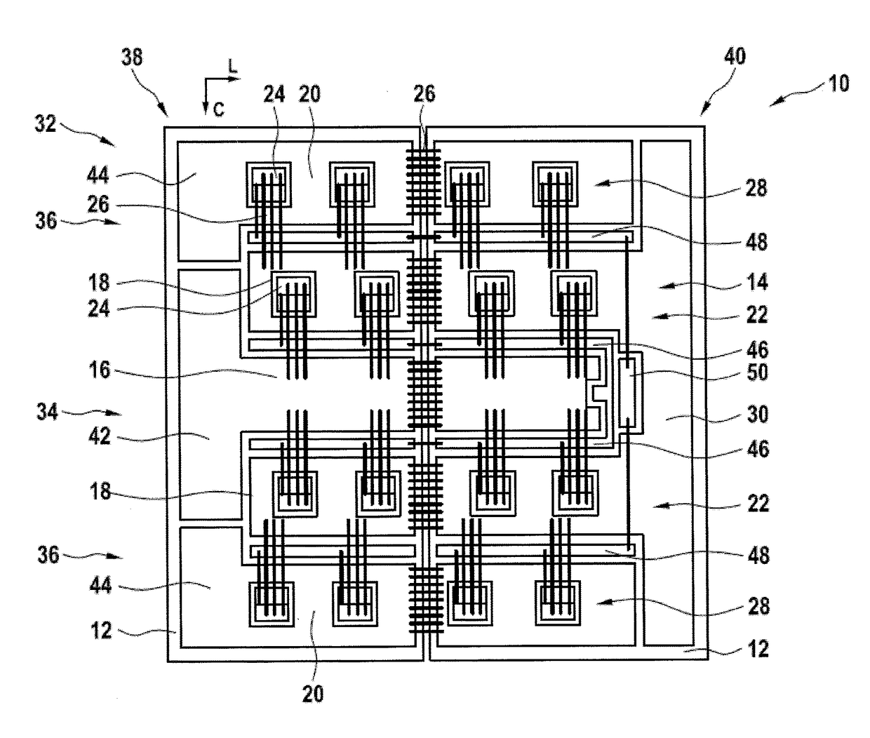
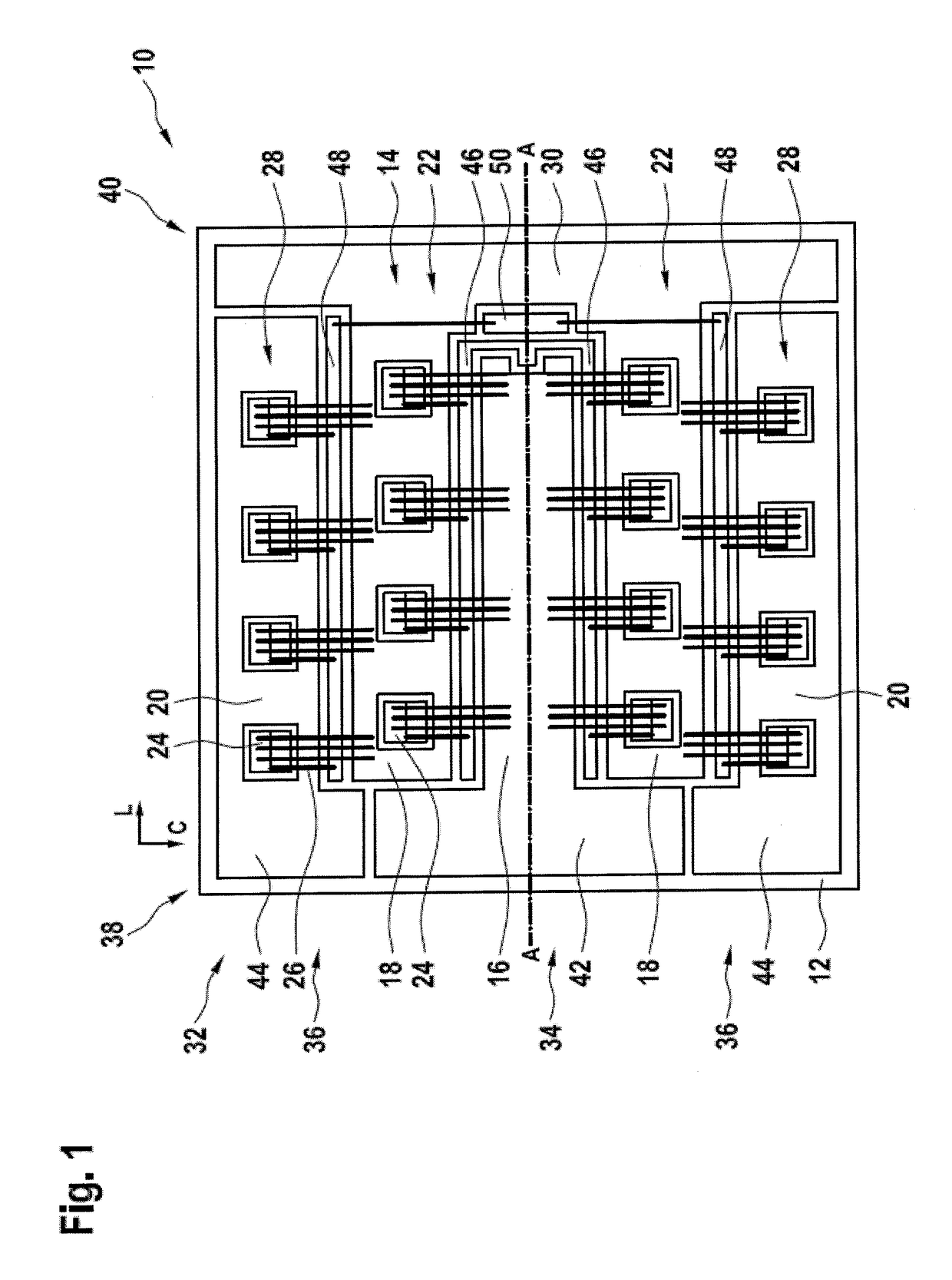
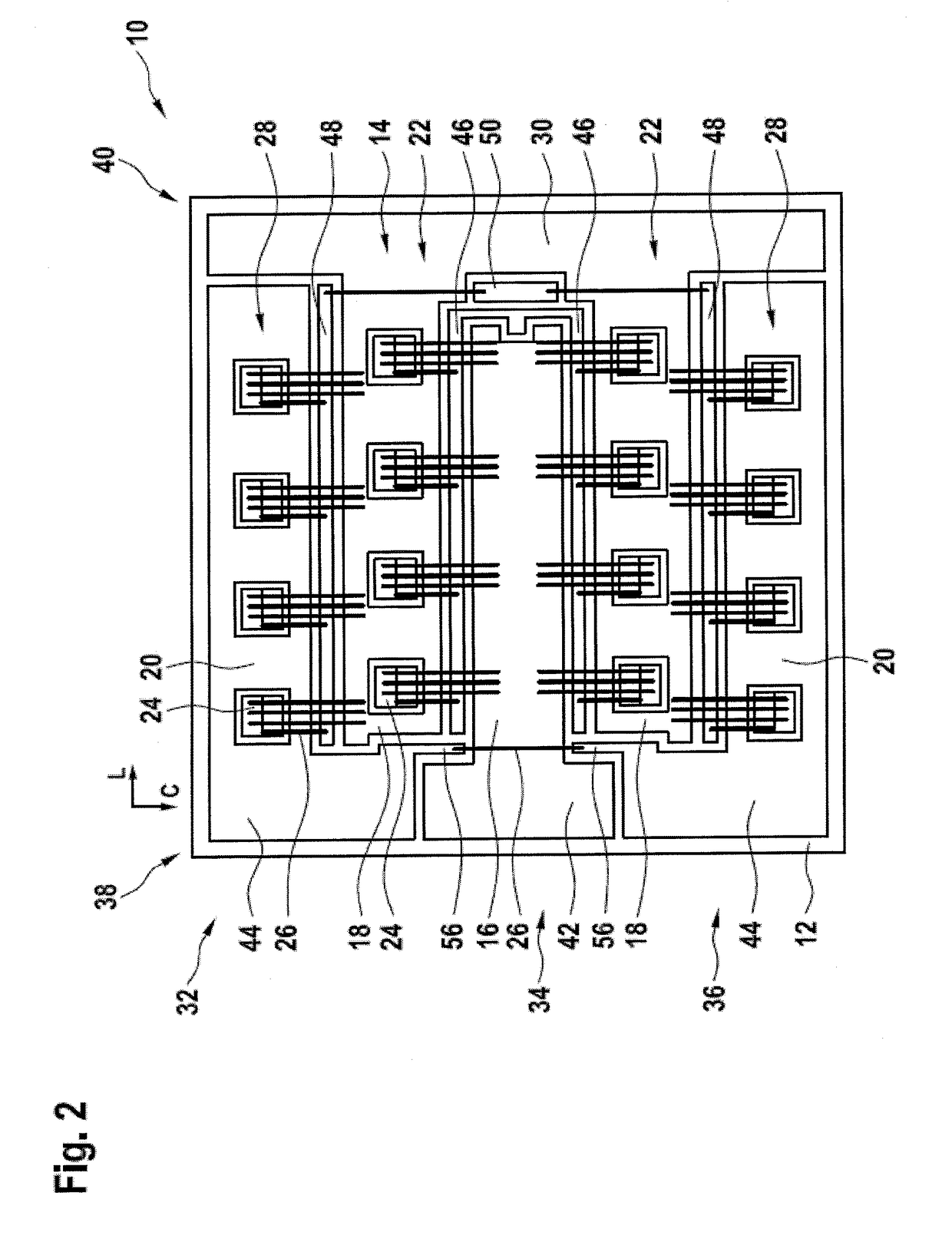
[0008]It is an objective of the invention to provide a power module with low stray inductance.
[0009]This objective is achieved by the subject-matter of the independent claims. Further exemplary embodiments are evident from the dependent claims and the following description.
[0010]An aspect of the invention relates to a power module providing a half bridge. A power module may be a device electrically and mechanically interconnecting a plurality of semiconductor switches. Usually, a power module comprises a substrate, which may have metallization layers on one or both sides to which the semiconductor switches are bonded. The substrate and the one or more metallization layers may be a DBC (direct bonded copper) substrate. Furthermore, the power module may comprise terminals, which also may be bonded to the metallization layers. The substrate, semiconductor switches and terminals may be cast into an encasing.
[0011]A half bridge may be an electrical circuit, comprising two switch elements...
PUM
 Abstract
Description
Claims
Application Information