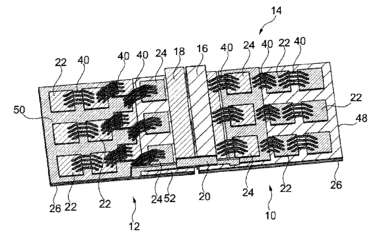
Power semiconductor module
a technology of semiconductor modules and semiconductor devices, applied in semiconductor devices, semiconductor/solid-state device details, electrical apparatus, etc., can solve the problems of limiting the maximum achievable switching time, stray inductance of standard planar power modules cannot be easily reduced to values below 5-10 nh, and is often not acceptable, so as to reduce stray inductance, reduce stray inductance, and facilitate module design.
- Summary
- Abstract
- Description
- Claims
- Application Information
AI Technical Summary
Benefits of technology
Problems solved by technology
Method used
Image
Examples
Embodiment Construction
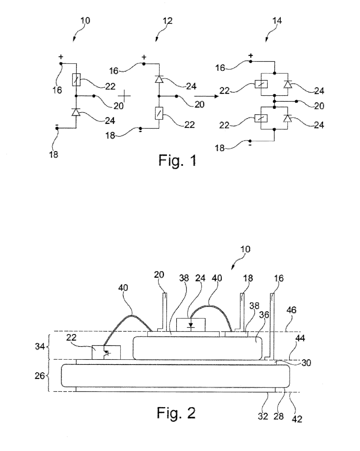
[0084]In FIG. 1, an embodiment of an electronic circuit topology is shown, which may be realized by means of the power semiconductor module according to the invention.
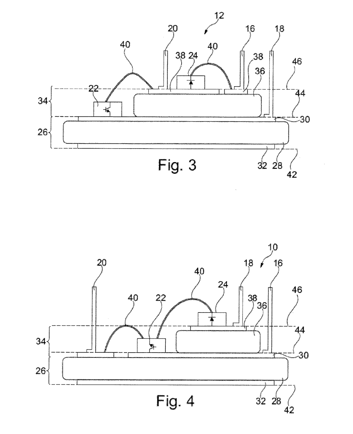
[0085]In detail, a P-cell 10 is shown as well as an N-cell 12, which may form a half-bridge module 14 in a parallel combination, or connection, respectively. Regarding the P-cell 10 and the N-cell 12, these cells comprise a DC+ terminal, or positive DC-connection 16 and a DC− terminal, or negative DC-connection 18, respectively, as well as an AC-connection 20. Further, a transistor 22 working as a switch is provided, which may be formed by a MOSFET, IGBT or the like. Additionally, a diode 24 is provided. Further, the AC-connection 20 is provided which, at the P-cell 10, may connect the circuit to the positive lead of a current-source or inductor and which, at the N-cell, may connect the circuit to the negative lead of a current-source or inductor.
[0086]As stated above, providing low stray inductance in a circuit may be...
PUM
 Abstract
Description
Claims
Application Information
 - R&D
- Intellectual Property
- Life Sciences
- Materials
- Tech Scout
- Unparalleled Data Quality
- Higher Quality Content
- 60% Fewer Hallucinations
Browse by: Latest US Patents, China's latest patents, Technical Efficacy Thesaurus, Application Domain, Technology Topic, Popular Technical Reports.
© 2025 PatSnap. All rights reserved.Legal|Privacy policy|Modern Slavery Act Transparency Statement|Sitemap|About US| Contact US: help@patsnap.com


