
Method for controlling rotation recognition unit of rotating body and electronic device thereof

a technology of rotation recognition unit and electronic device, which is applied in the field of electronic devices, can solve the problems of large amount of power consumption, narrow mounting space, and limit the implementation of functions, and achieve the effect of reducing power consumption and improving the usability of rotation recognition units

Inactive Publication Date: 2018-02-27
SAMSUNG ELECTRONICS CO LTD
View PDF8 Cites 4 Cited by
  • Summary
  • Abstract
  • Description
  • Claims
  • Application Information

AI Technical Summary

Benefits of technology

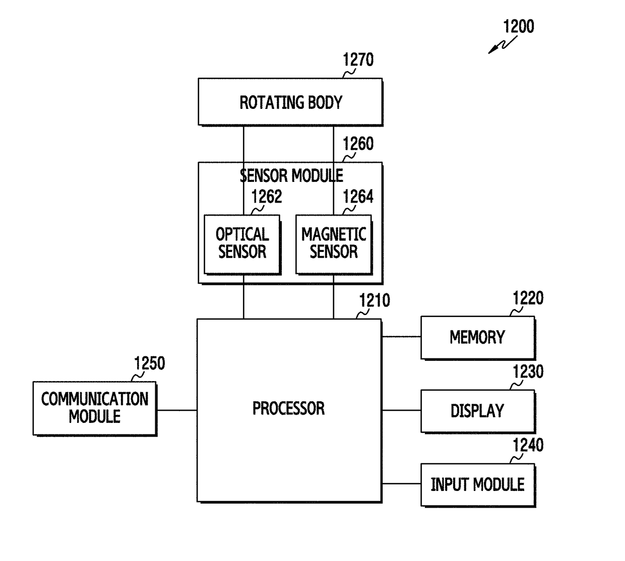
[0009]Various aspects of the present disclosure provide a device and method that reduces power consumption while improving the usability of a rotation recognition unit for recognizing the rotation of a rotating body in an electronic device.

Problems solved by technology

Wearable devices that may be worn on human bodies or various structures are formed to be relatively small and slim resulting in limitations in implementing functions thereof.
However, in cases where the electronic devices recognize the rotation of the rotating bodies using optical sensors, although the electronic devices may continuously and accurately recognize the rotation according to the extent of image analysis, a large amount of power is consumed due to the complexity and frequent use of the image analysis.
Further, in cases where the electronic devices recognize the rotation of the rotating bodies using magnetic sensors, although a small amount of power is consumed, mounting spaces become narrower due to the plurality of magnets and magnetic sensors, and the electronic devices may fail to continuously recognize the rotation so that usability thereof may deteriorate.

Method used


Image

  • Method for controlling rotation recognition unit of rotating body and electronic device thereof
  • Method for controlling rotation recognition unit of rotating body and electronic device thereof
  • Method for controlling rotation recognition unit of rotating body and electronic device thereof

Examples


Embodiment Construction

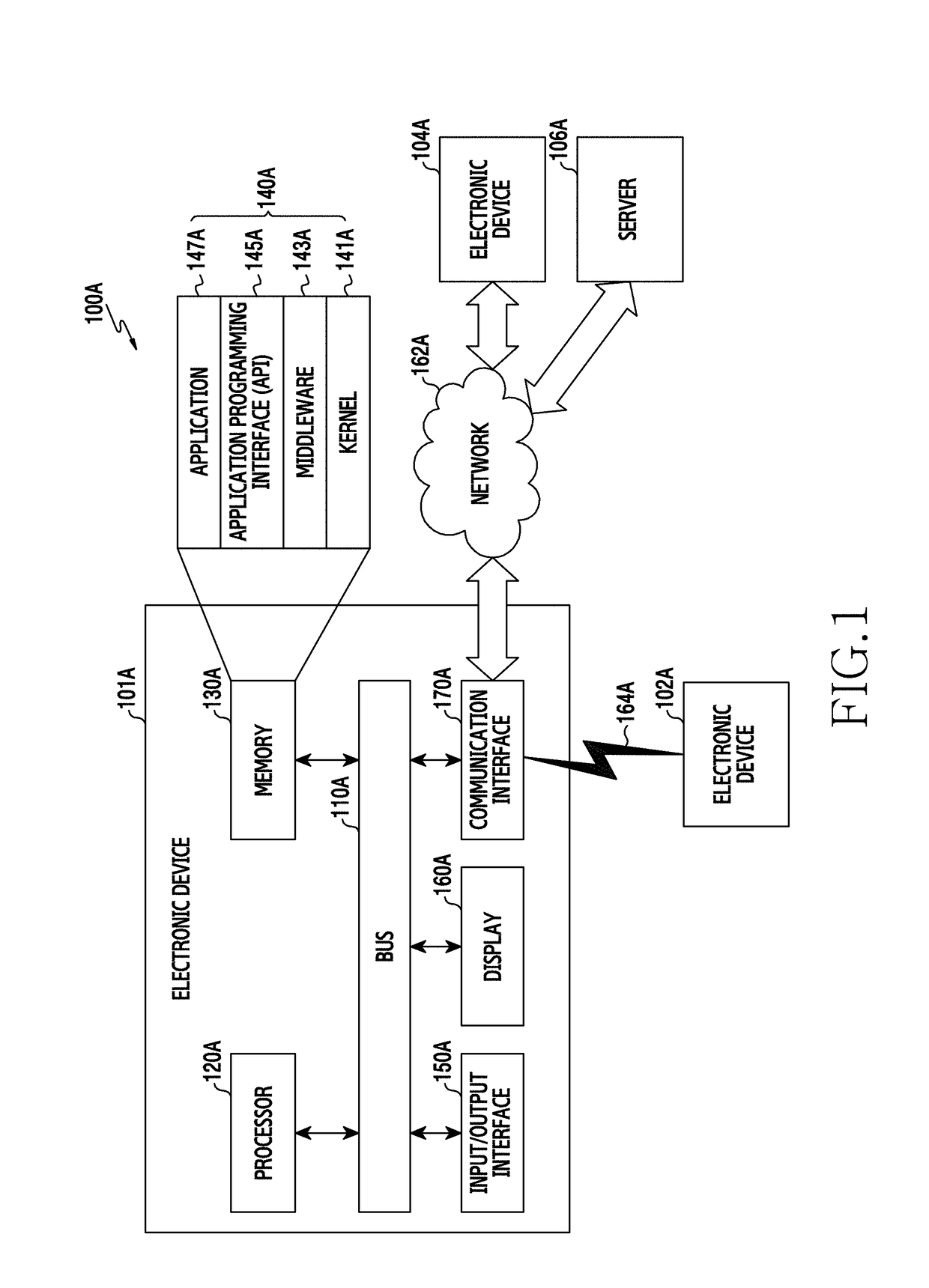
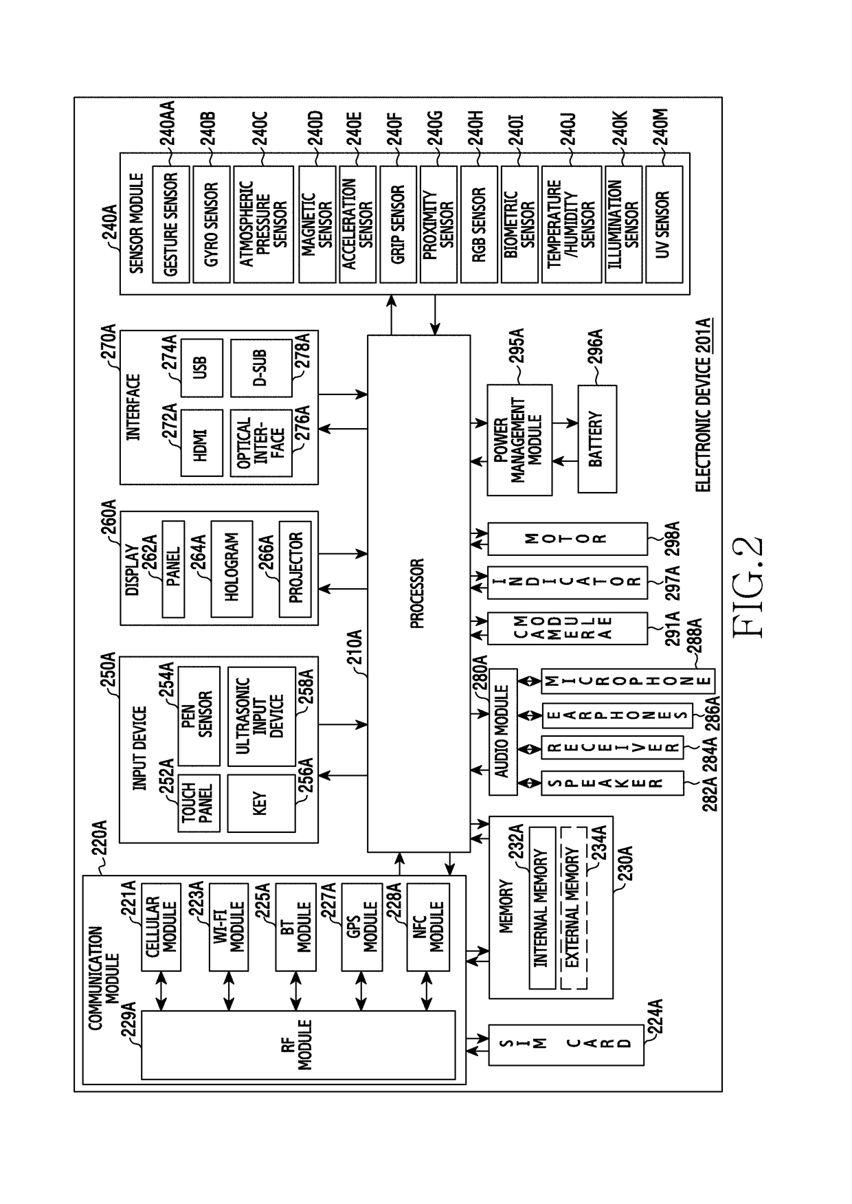
[0047]Hereinafter, various embodiments of the present disclosure will be described in detail with reference to the accompanying drawings. However, it should be understood that the various embodiments of the present disclosure are not limited to specific embodiments and include various modifications, equivalents, and / or alternatives thereof. In describing the drawings, similar reference numerals may be used to designate similar elements.

[0048]As used herein, the expressions “have”, “may have”, “include”, or “may include” refer to the existence of a corresponding feature (e.g., numeral, function, operation, or constituent element such as component), and do not exclude one or more additional features.

[0049]The expressions “A or B,”“at least one of A or / and B,”“one or more of A or / and B,” and the like may include all combinations of the listed items. For example, “A or B,”“at least one of A and B,” or “at least one of A or B” may refer to all cases of (1) including at least one A, (2) i...


PUM


Abstract

A device and method for controlling rotation recognition units that detect the rotation of a rotating body in an electronic device are presented. The electronic device includes an outer housing, a rotary member disposed adjacent to, or at least in partial contact with the housing, a first sensor that detects rotation of the rotary member relative to the housing through a first physical change, a second sensor that detects rotation of the rotary member relative to the housing through a second physical change, a battery disposed in the housing, a processor electrically connected to the battery, the first sensor, and the second sensor, and a memory electrically connected to the processor, wherein the memory stores instructions that, when executed, cause the processor to selectively control the operation of at least one of the first and second sensor based on at least one of the state of the electronic device and an application program that is being executed by the processor.

Description

PRIORITY[0001]This application claims priority under 35 U.S.C. § 119(a) to Korean Patent Application Serial No. 10-2015-0027856, which was filed in the Korean Intellectual Property Office on Feb. 27, 2015, the entire content of which is incorporated herein by reference.BACKGROUND[0002]1. Field of the Disclosure[0003]The present disclosure generally relates to an electronic device, and more particularly to a method for controlling a rotation recognition unit of a rotating body in an electronic device.[0004]2. Description of the Related Art[0005]Electronic devices have become smaller and slimmer and evolved to be easily carried while performing the same or more diverse functions. Although compact electronic devices are generally carried within users' pockets, they may be worn on the wrist, the head, or the arm of a human body.[0006]Wearable devices that may be worn on human bodies or various structures are formed to be relatively small and slim resulting in limitations in implementing...

Claims


Application Information

Patent Timeline
Patent Type & Authority Patents(United States)
IPC IPC(8): G06F3/0362G06F1/16G01D7/00G06F3/03G06F1/32G01D5/56G01D5/14G01D5/28
CPCG06F3/0362G01D5/145G01D5/28G01D5/56G06F1/325G06F1/3212G06F1/3287G06F3/0312G06F1/163Y02D10/171Y02D10/174Y02D50/20G01D7/007Y02D10/00Y02D30/50G06F3/01
Inventor PARK, HYUNG-JINYUN, HEE-YOUNG
Owner SAMSUNG ELECTRONICS CO LTD
Learn More