Molding die, optical element manufacturing method, and optical element

a technology of optical elements and manufacturing methods, applied in the field of molding dies, optical element manufacturing methods, optical elements, etc., can solve the problems of difficult machining, difficult to ensure the space in which the ejector pin is provided, and difficult to ensure the reproducibility of molding while the product portion is pushed out, so as to prevent the concentration of stress on the connecting and prevent the bending or rupture of the gate portion at the time of mold releasing

Inactive Publication Date: 2018-03-13
KONICA MINOLTA INC
View PDF28 Cites 0 Cited by
  • Summary
  • Abstract
  • Description
  • Claims
  • Application Information

AI Technical Summary

Benefits of technology

[0018]The present invention has an object to provide a molding die which can easily release a minute optical element in a state of favorable surface accuracy, while preventing bending or rupture of a gate portion attached to the optical element even when only a flow channel portion such as a runner portion in a molding product is pushed out.

Problems solved by technology

In the method of Patent Literature 1, when the product portion is minute, it is difficult to ensure a space in which the ejector pin is provided.
In addition, also the configuration in which the core portion forming the product portion is pushed out has limitation in reducing a thickness or a size of the core portion in accordance with the product portion, and machining is difficult.
Furthermore, even if such a core portion can be machined, rigidity of the core portion cannot be ensured, and molding with good reproducibility while the product portion is pushed out is difficult.
In the method of Patent Literature 2, when the product portion is minute, the flange portion is also minute, and provision of the protruding portion is difficult.
In addition, when the protruding portion is to be provided on the side opposite to the gate portion, in the minute product portion, after a resin is filled in the projection portion, the resin is instantaneously cooled and solidified, whereby formation of the projection portion is made difficult.
However, a stress is applied to the gate portion attached to the product portion at the time of pushing-out, and it is likely that bending or rupture occurs.
As a result, there is a risk that a crack occurs in the gate portion, the gate portion is ruptured, and taking-out of the product portion becomes difficult.
With the shape of the gate portion in Patent Literature 3, the shape of the gate portion becomes wide with respect to the product portion, and gate cutting along the outer shape of the product portion becomes difficult.
Namely, even if the gate cutting is performed, a part of the gate portion remains largely in many cases, and when the product portion is to be assembled to a holder or the like, restriction on a recess shape of the gate portion on the holder side becomes large.
In the minute product portion, when a mold surface is deep, and an outer circumferential side surface of the product portion is perpendicular or substantially perpendicular to a mold mating surface, even if the runner portion is pushed out in the diagonal direction without providing a mechanism for pushing out the product portion, there is a risk that an outer circumferential portion of the product portion is caught by the die, and bending and rupture occur in the gate portion.

Method used


Image

  • Molding die, optical element manufacturing method, and optical element
  • Molding die, optical element manufacturing method, and optical element
  • Molding die, optical element manufacturing method, and optical element

Examples


first embodiment

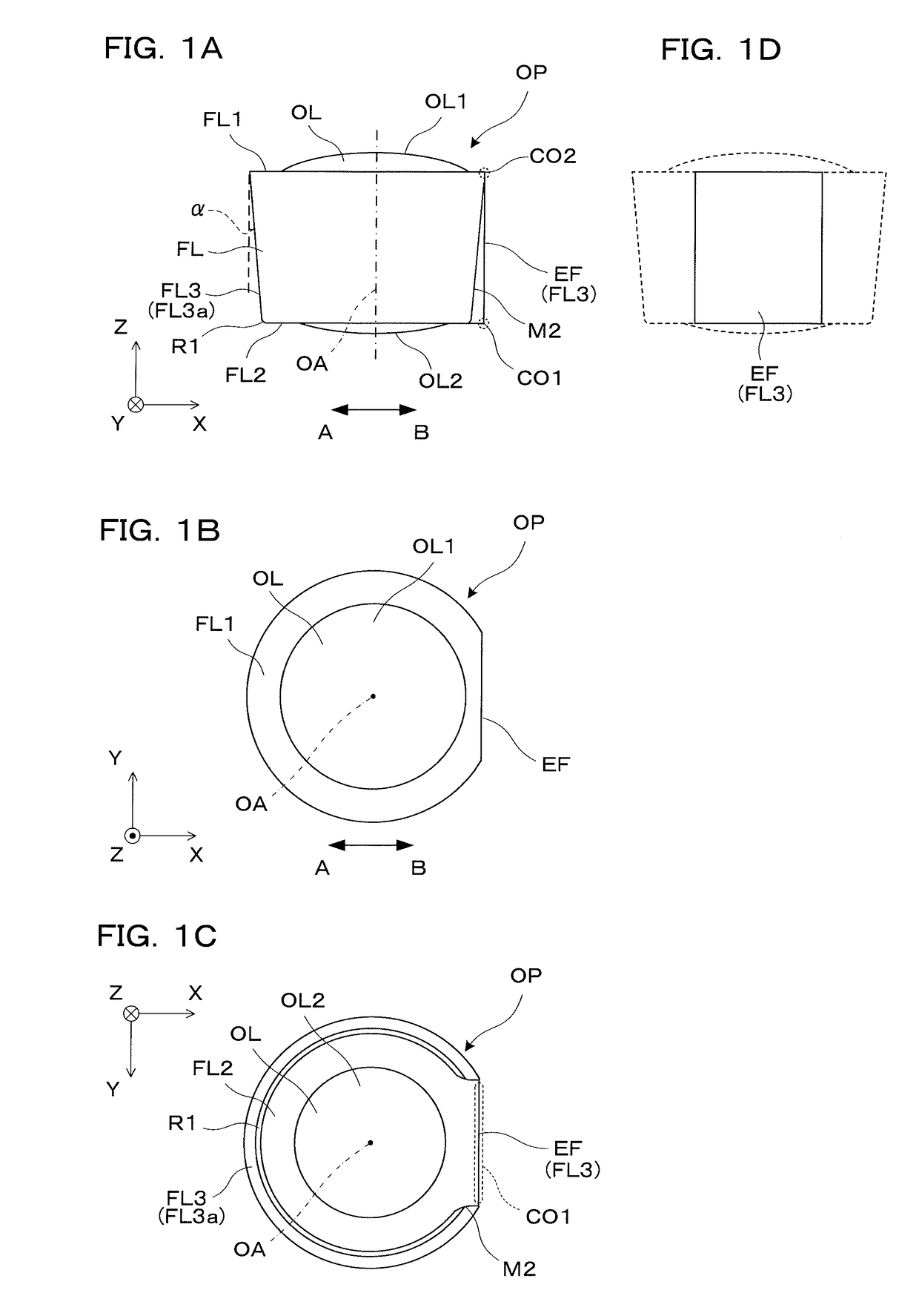
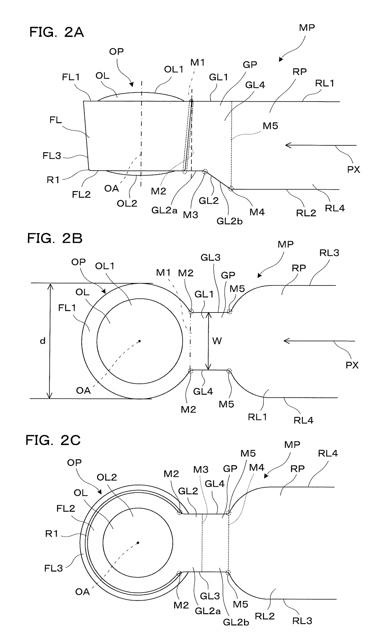
[0041]An optical element of a first embodiment according to the present invention will be described by referring to FIGS. 1A to 1D. A lens OP which is an optical element is a small-sized lens made of a resin and is used as, for example, an objective lens of an optical pickup device (specifically, a lens exclusively used for BD (Blu-ray Disc: trademark)) or a lens for an endoscope. The lens OP is obtained by cutting a gate portion GP in a molding product MP shown in FIGS. 2A to 2C.

[0042]The lens OP has an optical portion OL having an optical function and an annular outer circumferential portion FL extending from the optical portion OL to an outer diameter direction. In the lens OP, the optical portion OL has a convex first optical surface OL1 and a convex second optical surface OL2. Namely, the optical portion OL is thicker on a center side. The first optical surface OL1 and the second optical surface OL2 are generally smooth and face each other by sandwiching a body (center of the l...

second embodiment

[0066]Hereinafter, a molding die and the like of a second embodiment will be described. The molding die and the like of the second embodiment are a modification of the molding die and the like of the first embodiment, and the matters not particularly described are similar to those in the first embodiment.

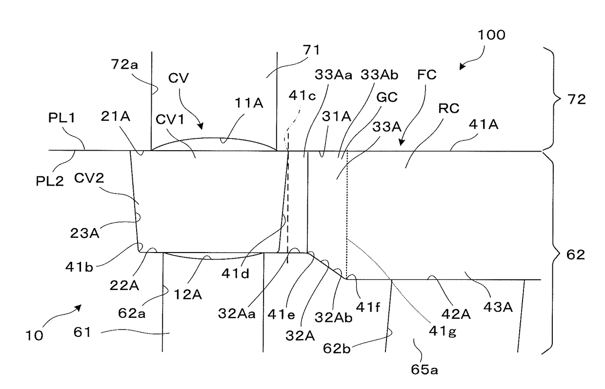
[0067]As shown in FIGS. 6A and 6B, in the movable die 10, the second gate-forming surface 32A of the gate-forming portion GC has the first transfer surface 32Aa extending outward from the second outer circumferential transfer surface 22A and parallel to the mold mating surface PL1, and the second transfer surface 32Ab extending outward from the first transfer surface 32Aa and inclined to the first transfer surface 32Aa. Furthermore, the gate side surface-forming surfaces 33A and 34A of the gate-forming portion GC have third transfer surfaces 33Aa and 34Aa extending outward from the side-surface transfer surface 23A and perpendicular to the portion 41c connecting the mold mating surf...

third embodiment

[0069]Hereinafter, a molding die and the like of a third embodiment will be described. The molding die and the like of the third embodiment are a modification of the molding die and the like of the first embodiment, and the matters not particularly described are similar to those in the first embodiment.

[0070]As shown in FIGS. 7A and 7B, in the movable die 10, the second gate-forming surface 32A of the gate-forming portion GC has a gentle curved surface from the second outer circumferential transfer surface 22A side to the second runner-forming surface 42A side. Namely, in the movable die 10, the gate-forming portion GC has its depth increasing as going from the outer circumference-forming portion CV2 side toward the runner-forming portion RC side.

[0071]As shown in FIG. 7C, the molding product MP molded by the molding die 100 shown in FIGS. 7A and 7B has the second gate surface GL2 formed as a gentle curved surface with the thickness increasing as going from the outer circumferential...


PUM

PropertyMeasurementUnit
taper angleaaaaaaaaaa
R-shapeaaaaaaaaaa
taper angleaaaaaaaaaa

Abstract

Technique to provide a molding die which can easily release a minute optical element in a state of favorable surface accuracy, while bending or rupture of a gate portion attached to the optical element is prevented. By making a first outer circumferential transfer surface 21A of a fixed die 20 and a first gate-forming surface 31A flush with each other, a notch shape is not formed on a portion M1 connecting an outer circumferential portion FL on the fixed die 20 side and a gate portion GP. Furthermore, by pushing out the runner portion RP at the same angle as a taper angle α of a side-surface transfer surface 23A on a second gate-forming surface 32A side, bending deformation or the like of the gate portion GP which can occur when being pushed out to a direction perpendicular to a mold mating surface PL1 can be prevented.

Description

RELATED APPLICATIONS[0001]This is a U.S. National Phase Application under 35 USC 371 of International Application PCT / JP2013 / 073984 filed on Sep. 5, 2013.[0002]This application claims the priority of Japanese application no. 2012-204241 filed Sep. 18, 2012, the entire content of which is hereby incorporated by reference.TECHNICAL FIELD[0003]The present invention relates to a molding die for molding a minute optical element, an optical element manufacturing method using the molding die, and an optical element manufactured by using the molding die.BACKGROUND ART[0004]As a method for releasing a molding product including an optical element which is a product portion from a molding die, a method in which an ejector pin or a core portion for forming the product portion, added to the die, is pushed out toward an opposing die side and the product portion is released with a gate portion and a runner portion, attached to this product portion, is known (refer to, for example, Patent Literatur...

Claims


Application Information

Patent Timeline
Patent Type & Authority Patents(United States)
IPC IPC(8): B29C45/40B29D11/00G02B3/00B29C45/27B29C45/38B29L11/00
CPCB29C45/4005B29C45/2708B29C45/38G02B3/00B29D11/00413B29L2011/0016B29C45/401
Inventor HARA, SHINICHIROAKUTSU, DAIMORI, HAJIME
Owner KONICA MINOLTA INC
Why Eureka
Try Eureka