Interlocking needle hub and catheter hub actuator to increase rigidity of iv catheter assembly

a technology of iv catheter and actuator, which is applied in the direction of catheters, other medical devices, and guide needles, etc., can solve the problems of limited options, limited flexibility between components, and difficulty of clinicians, so as to increase the vertical rigid increase the rigidity of the catheter assembly, and increase the vertical rigidity

Active Publication Date: 2015-02-05
BECTON DICKINSON & CO
View PDF7 Cites 65 Cited by
  • Summary
  • Abstract
  • Description
  • Claims
  • Application Information

AI Technical Summary

Benefits of technology

[0011]The present invention extends to a design of a needle hub and an actuator of a catheter assembly that allows the needle hub and actuator to interlock within the catheter hub. This interlocking allows the needle hub to be inserted into the catheter hub thereby increasing the rigidity of the catheter assembly. The interlocking can be accomplished by forming one or more channels in the proximal end of the actuator and one or more corresponding protrusions that extend from the distal end of the needle hub. In some embodiments, the channels and protrusions can be formed at the top and bottom of the catheter hub and needle hub respectively to thereby increase the vertical rigidity of the catheter assembly. The increase in vertical rigidity can prevent flexing of the catheter hub with respect to the needle shield when a downward force is applied to the catheter assembly such as is common during insertion of the needle.
[0012]In some embodiments, the present invention is implemented as a catheter assembly comprising a catheter hub and a needle shield. The catheter hub contains an actuator and a septum. The actuator is configured to pierce the septum when a force is applied to the actuator. The needle shield is connected to the catheter hub and contains a needle hub. The needle hub contains a needle that extends through the catheter hub. The needle hub also includes one or more protrusions that extend from a distal end of the needle hub while the actuator includes one or more channels that extend from a proximal end and into the actuator. The one or more protrusions of the needle hub insert into the one or more channels thereby interlocking the needle hub with the actuator to provide greater rigidity between the catheter hub and the needle shield.
[0013]In some embodiments, the actuator includes two channels and the needle hub includes two protrusions. These channels can be positioned at the top and bottom of the actuator to provide greater rigidity against vertical forces applied to the catheter assembly.
[0017]In other embodiments, the present invention is implemented as an actuator for use within a catheter hub. The actuator comprises a main body extending from a distal end to a proximal end. The distal end is configured to pierce a septum when a force is applied to the proximal end. The proximal end includes one or more channels that extend towards the distal end. The one or more channels are sized and shaped to receive one or more protrusions of a needle hub contained within a needle shield to thereby interlock the actuator and the needle hub to provide greater rigidity between the catheter hub and the needle shield.
[0018]In some embodiments, the proximal end of the actuator includes two channels. The two channels may be positioned at the top and bottom of the proximal end to provide greater rigidity against vertical forces.

Problems solved by technology

If this amount of flexibility is too great, the clinician may experience difficulty when inserting needle 102 into the patient's vasculature.
Because of this, there are limited options for reinforcing the connection between catheter hub 101 and needle shield 103 to limit the amount of flexibility between the components when needle 102 is inserted.
Because the actuator is positioned near the proximal end of the catheter hub, there is little area for providing structural reinforcements inside the catheter hub.
Because this portion is relatively short and thin, it cannot provide significant strength to withstand the flexing forces.
As a result, an undesirable amount of flexing often occurs.
The flexing between the catheter hub and the needle shield creates various problems.
Primarily, when the components flex, the amount of force transferred to the needle is reduced thereby making it more difficult to insert the needle through the patient's skin.
Also, when this flexing occurs, the clinician perceives the components as being weak which may cause the clinician to alter the catheter insertion procedure or to view the catheter assembly as being unsatisfactory.
In some cases, this flexing may also lead to failure of the components.

Method used


Image

  • Interlocking needle hub and catheter hub actuator to increase rigidity of iv catheter assembly
  • Interlocking needle hub and catheter hub actuator to increase rigidity of iv catheter assembly
  • Interlocking needle hub and catheter hub actuator to increase rigidity of iv catheter assembly

Examples


Embodiment Construction

[0042]The presently preferred embodiments of the present invention will be best understood by reference to the drawings, wherein like reference numbers indicate identical or functionally similar elements. It will be readily understood that the components of the present invention, as generally described and illustrated in the figures herein, could be arranged and designed in a wide variety of different configurations. Thus, the following more detailed description, as represented in the figures, is not intended to limit the scope of the invention as claimed, but is merely representative of presently preferred embodiments of the invention.

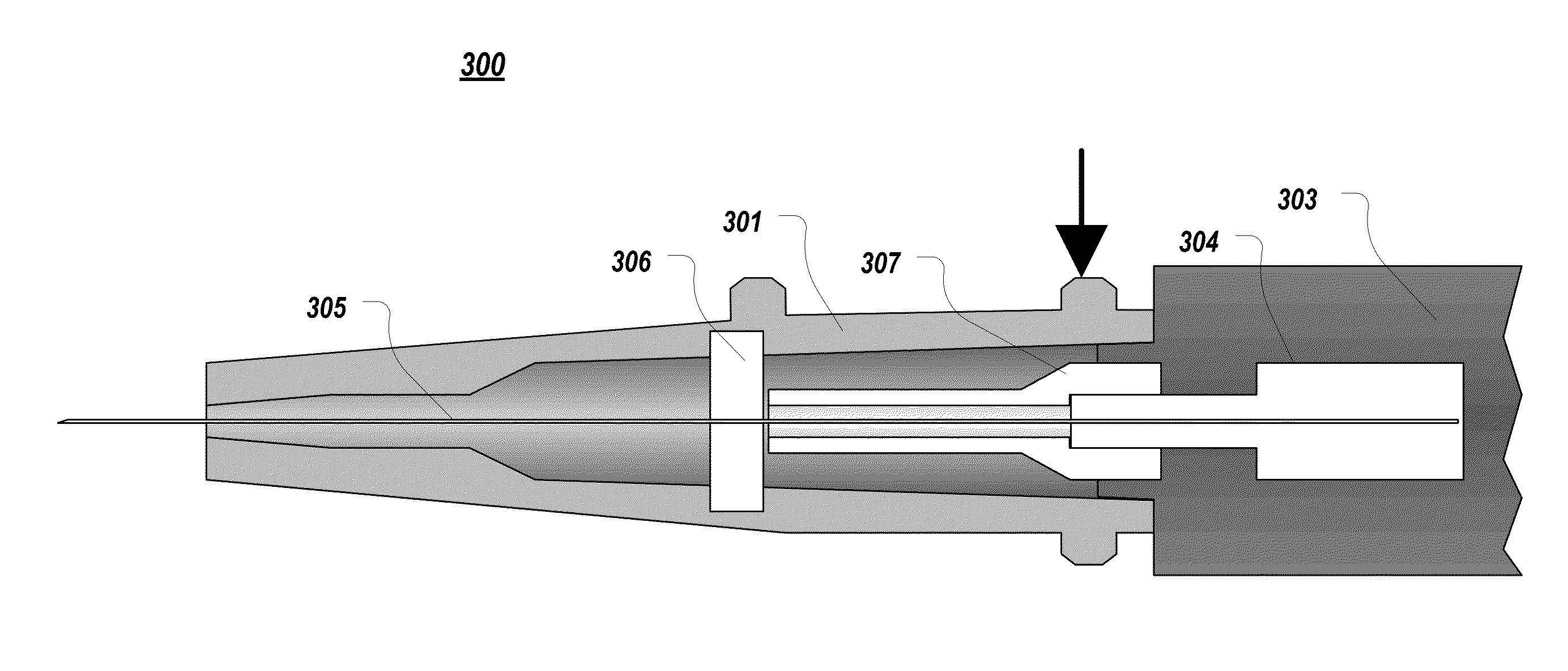
[0043]The present invention extends to a design of a needle hub and an actuator of a catheter assembly that allows the needle hub and actuator to interlock within the catheter hub. This interlocking allows the needle hub to be inserted into the catheter hub thereby increasing the rigidity of the catheter assembly. The interlocking can be accomplished ...


PUM


Abstract

The present invention extends to a design of a needle hub and an actuator of a catheter assembly that allows the needle hub and actuator to interlock within the catheter hub. This interlocking allows the needle hub to be inserted into the catheter hub thereby increasing the rigidity of the catheter assembly. The interlocking can be accomplished by forming channels in the proximal end of the actuator and corresponding protrusions from the distal end of the needle hub. In some embodiments, the channels and protrusions can be formed at the top and bottom of the catheter hub and needle hub respectively to thereby increase the vertical rigidity of the catheter assembly. The increase in vertical rigidity can prevent flexing of the catheter hub with respect to the needle shield when a downward force is applied to the catheter assembly such as is common during insertion of the needle.

Description

BACKGROUND OF THE INVENTION[0001]The present invention relates generally to intravenous (IV) catheter assemblies and particularly to increasing the rigidity between a catheter hub and a needle shield of the assembly to facilitate the threading of the catheter.[0002]FIG. 1 illustrates a common IV catheter assembly 100 that consists of a catheter hub 101 and a needle shield 103. Needle shield 103 contains a needle hub from which a needle 102 extends. Needle 102 extends through catheter hub 101 and is used to thread the catheter into the vasculature of a patient. IV catheter assembly 100 is initially handled by a clinician as a single component. The clinician inserts needle 102 into the patient's vasculature and then slides the catheter over top of the needle further into the vasculature. Once the catheter is placed appropriately in the vasculature, needle 102 can be retracted into needle shield 103. Then, needle shield 103 can be detached from catheter hub 101 leaving catheter hub 101...

Claims


Application Information

Patent Timeline
Patent Type & Authority Applications(United States)
IPC IPC(8): A61M25/06A61M25/00
CPCA61M25/0606A61M25/0625A61M2205/10A61M25/008A61M25/0097A61M25/0631A61M2039/226
Inventor CHRISTENSEN, COREY M.BORNHOFT, STEPHEN T.
Owner BECTON DICKINSON & CO
Why Eureka
Try Eureka