Inductive steering torque and angle sensor

a technology of torque and angle sensor, which is applied in the direction of force/torque/work measurement apparatus, instruments, transportation and packaging, etc., can solve the problems of requiring additional computing resources, two inductive position sensor in the same area interfere with each other, and it is difficult to extract the torsion angle from the two outputs of the receiver coil, so as to achieve the effect of eliminating interferen

Active Publication Date: 2018-03-13
KSR IP HLDG
View PDF7 Cites 0 Cited by
  • Summary
  • Abstract
  • Description
  • Claims
  • Application Information

AI Technical Summary

Benefits of technology

[0015]In order to minimize the electrical interference between the two receiver coils and thus the two sensors, the two receiving coils are constructed on the PCB on a different diameter so that the receiving coil associated with the first coupler does not overlap the receiving coil associated with the second coupler.
[0017]In order to further electrically isolate the two sensors from each other, a ferrite sheet underlies both sensors on both sides of the PCB. The ferrite sheet acts as a magnetic shield which effectively eliminates interference between the two sensors.

Problems solved by technology

One disadvantage of these previously known inductive sensors, however, is that the two inductive position sensors in the same area interfere with each other since they are both subjected to the same electromagnetic field.
In that event, it is difficult to extract the torsion angle from the two outputs from the receiver coils.
This, however, required additional computing resources since the mixed signals must be decoupled by certain algorithms.

Method used


Image

  • Inductive steering torque and angle sensor
  • Inductive steering torque and angle sensor
  • Inductive steering torque and angle sensor

Examples


Embodiment Construction

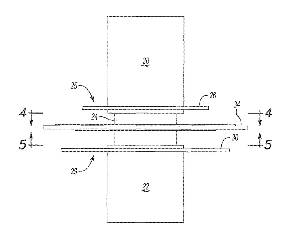
[0029]With reference first to FIG. 1, a portion of a steering wheel mechanism of the type used in automotive vehicles is shown. The steering wheel mechanism includes an input shaft 20 which is attached to the steering wheel for the vehicle. An output shaft 22 is coaxial with the input shaft 20. The output shaft 22 is connected to the steering linkage for the vehicle to provide the actual pivoting of the vehicle wheels.

[0030]The input shaft 20 and output shaft 22 are connected together by a torsion bar 24. This torsion bar 24 permits a limited amount of angular deflection between the input shaft 20 and the output shaft 22 depending upon the torque applied to the steering wheel. Typically, the angular deflection between the input shaft 20 and output shaft 22 rarely exceeds 20 degrees and more typically is in the range of 10 degrees or less.

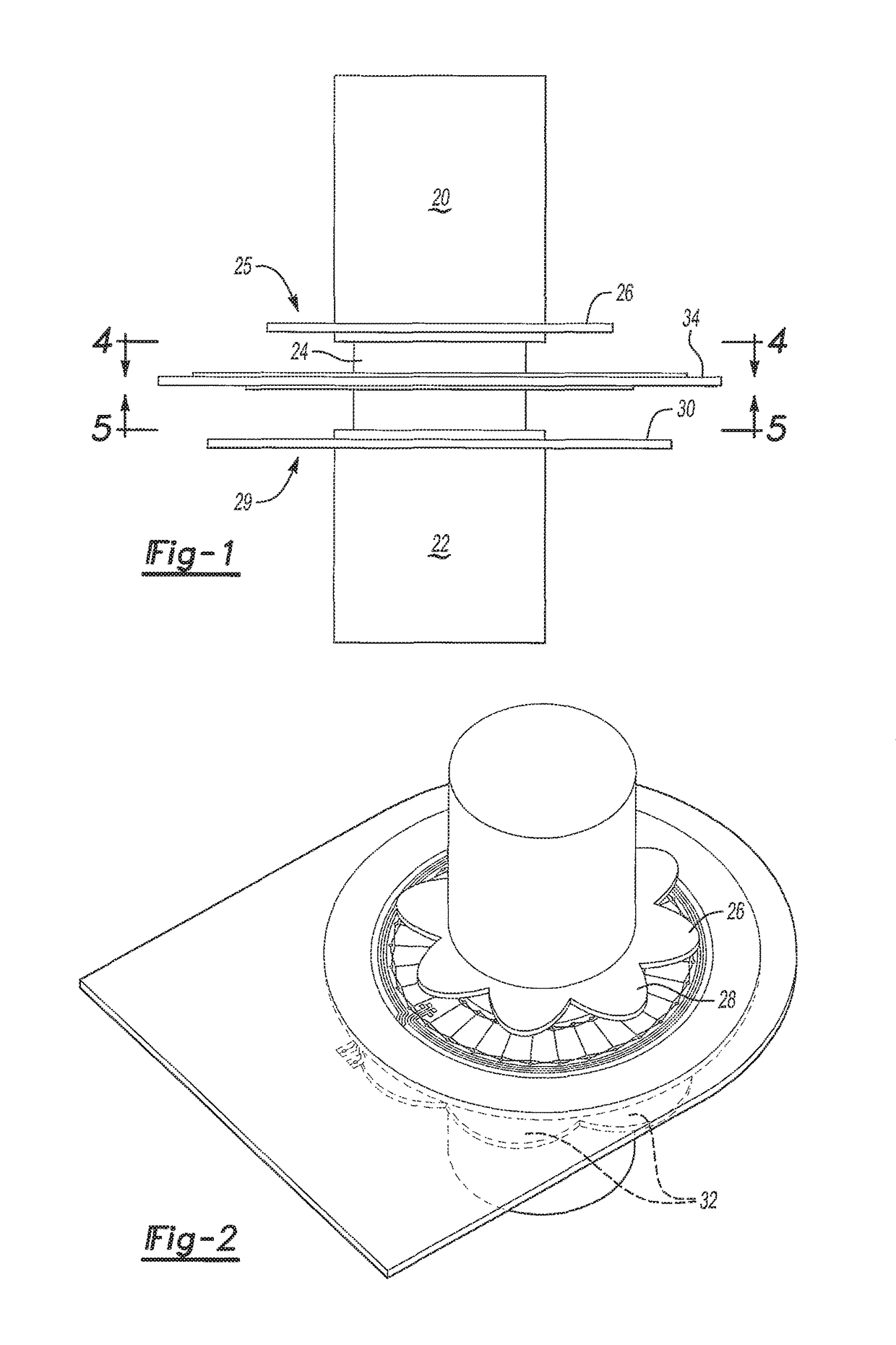
[0031]With reference now to FIGS. 1 and 2, a first inductive sensor 25 includes a first electrically conductive rotor or coupler 26 is attached to ...


PUM

PropertyMeasurementUnit
electrically conductiveaaaaaaaaaa
frequencyaaaaaaaaaa
torqueaaaaaaaaaa

Abstract

A torque sensor for a steering mechanism having an input shaft joined to an output shaft by a torsion bar. A first coupler is connected to the input shaft while a second coupler is connected to the output shaft. A first and second receiving coils, each having a plurality of oppositely wound loops, are arranged adjacent the first and second coils, respectively, while a circuit determines the angular offset between the couplers.

Description

CROSS-REFERENCE TO RELATED APPLICATIONS[0001]This application claims priority to U.S. Patent Application No. 62 / 277,098, entitled “Inductive Steering Torque and Angle Sensor”, filed Jan. 11, 2016, and also U.S. Patent Application No. 62 / 265,687, entitled “Inductive Steering Torque and Angle Sensor”, filed Dec. 10, 2015.BACKGROUND OF THE INVENTION[0002]I. Field of the Invention[0003]The present invention relates generally to a torque and angle sensor for a steering system.[0004]II. Description of Related Art[0005]In steering systems of the type used in automotive vehicles, the steering system typically includes an input shaft connected to the steering wheel. The input shaft is then connected to an output shaft through a torsion bar and the output shaft, in turn, is mechanically connected through linkage to the vehicle wheels. Consequently, rotation of the steering wheel pivots the wheels of the automotive vehicle through the torsion bar, output shaft, and steering linkage.[0006]In ma...

Claims


Application Information

Patent Timeline
Patent Type & Authority Patents(United States)
IPC IPC(8): B62D6/10G01L3/10
CPCG01L3/105B62D6/10G01L5/221
Inventor SHAO, LINGMINYANG, JUNELLIOTT, RYAN W.
Owner KSR IP HLDG
Why Eureka
Try Eureka