Apparatus and method for detecting metallic objects in shoes

a technology for detecting metallic objects and shoes, applied in the field of security inspection systems, can solve the problems of inconvenience for passengers, slow the rate of security checkpoint throughput, and consume time, and achieve the effect of reducing electrical interferen

Inactive Publication Date: 2008-05-15
MORPHO DETECTION INC
View PDF10 Cites 19 Cited by
  • Summary
  • Abstract
  • Description
  • Claims
  • Application Information

AI Technical Summary

Benefits of technology

[0009]The technology disclosed herein overcomes the disadvantages associated with the related art and meets the needs discussed above by providing an inspection system that, among other advantages and technical effects: positions a balancing shim to asymmetrically balance a magnetic field generated by an inductive sensor; symmetrically positions geometric arrangements of switches and relays used to operate the inductive sensor to minimize electrical interference; provides a shielding device that protects a magnetic field generated by the inductive shoe sensor from internal and external electrical interference; and positions a slot in an inductive sensor to tune a resonant mode of the inductive sensor to accurately and particularly detect metallic shanks in shoes.

Problems solved by technology

Such methods consume time, inconvenience passengers, and slow the rate of a security checkpoint's throughput.
Any metallic object or substance that is later positioned within the scanning area will disturb the otherwise balanced magnetic field generated by the metal detection conductive traces.
This disturbance creates an electrical and / or magnetic imbalance between the metal detector conductive traces, which causes the passenger screening system to receive a signal indicating that a metallic object has been detected within the scanning area.
Principal among them is that the magnetic field becomes imbalanced when the channel is capped by a kiosk and / or an end wall.
Additionally, the magnetic field degrades if not effectively shielded from at least the electric component of internal and / or external electromagnetic fields.

Method used


Image

  • Apparatus and method for detecting metallic objects in shoes
  • Apparatus and method for detecting metallic objects in shoes
  • Apparatus and method for detecting metallic objects in shoes

Examples


Embodiment Construction

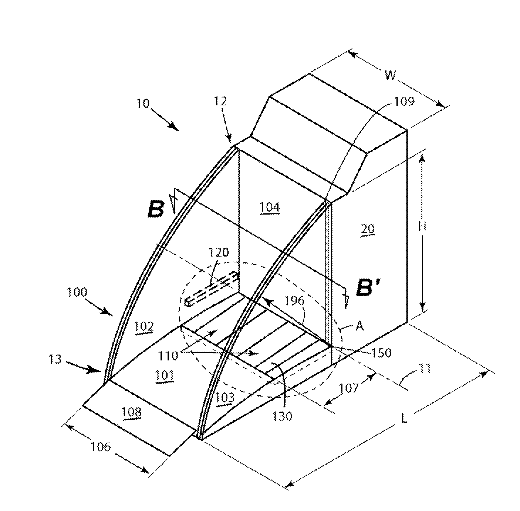
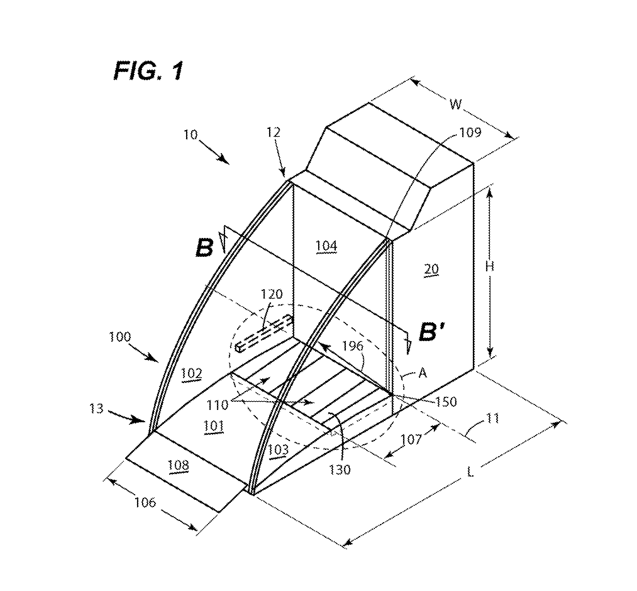
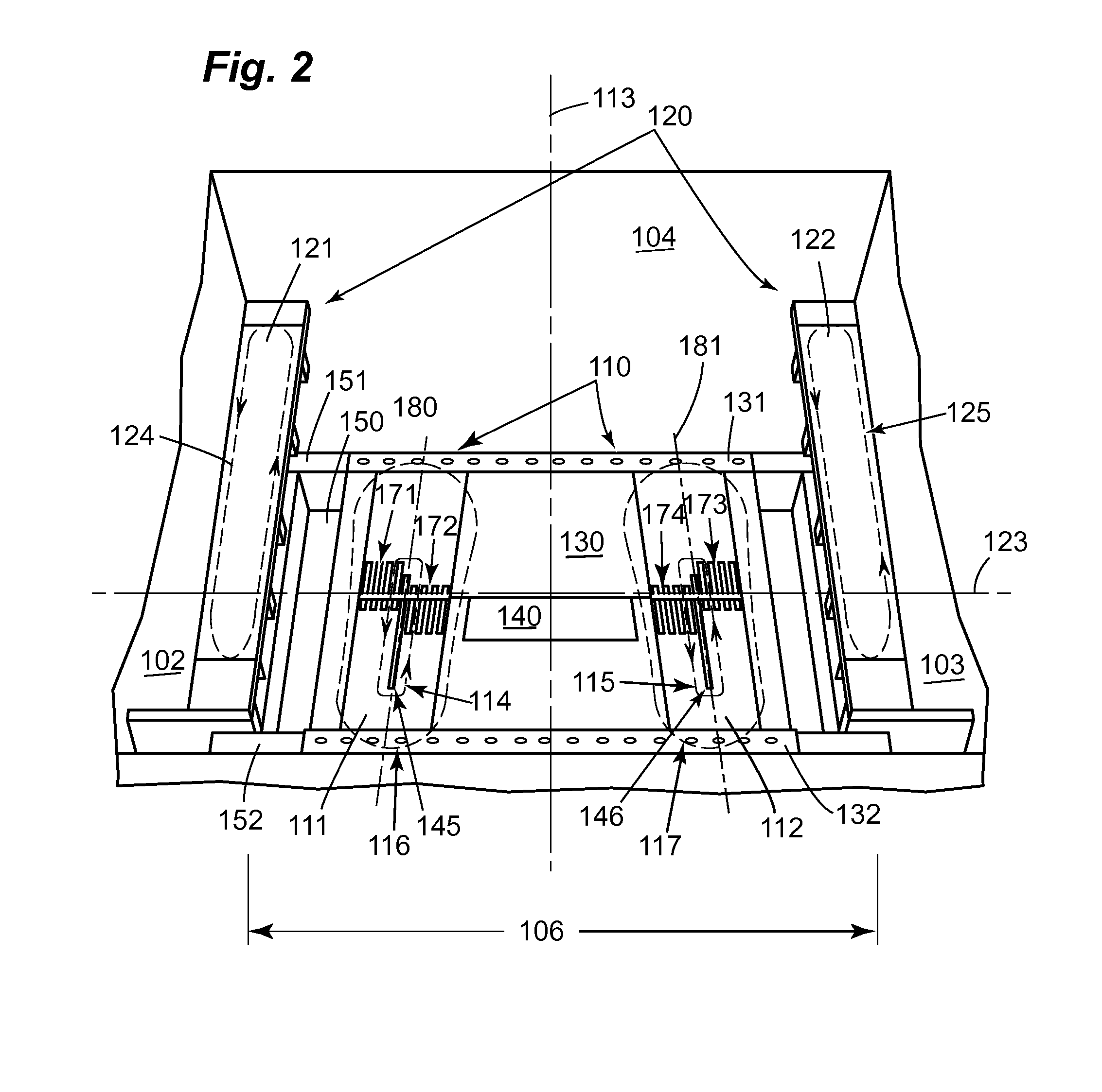
[0025]Reference is made herein to the accompanying drawings briefly described above, which show by way of illustration various embodiments of the claimed invention. Persons of ordinary skill in the above-referenced technological field will recognize that other embodiments may be utilized, and that structural, electrical, and procedural changes may be made without departing from the scope of the claimed invention. As used herein, the singular (illustratively, “shoe”) includes the plural (illustratively, “shoes”), and the plural includes the singular. As used herein, the term “shoe” comprises any type of natural or man-made article that can be worn on the entirety or a portion of a human leg. As used herein, the term “kiosk” comprises an area or structure, open on one or more sides, that is configured for one or more special uses that are described herein. Non-limiting examples of such special uses include identity card identification and / or biometric identification of a registered tr...


PUM

PropertyMeasurementUnit
widthaaaaaaaaaa
widthaaaaaaaaaa
lengthaaaaaaaaaa

Abstract

An inspection system positions a balancing shim to asymmetrically balance a magnetic field generated by an inductive sensor, which forms part of the inspection system. Additionally, relays and capacitors used to tune the inductive sensor to a desired resonance frequency are geometrically arranged to minimize electrical interference generated by operation of the relays and capacitors. A shielding device, which may be formed on a printed circuit board, protects a magnetic field generated by the inductive sensor from external electromagnetic interference. A slot positioned in the inductive sensor may be used to tune a resonant mode of the inductive sensor to accurately and particularly detect metallic shanks and/or other metallic objects in shoes, socks, and/or clothing.

Description

BACKGROUND OF THE INVENTION[0001]1. Field of the Invention[0002]The field of the invention relates to security inspection systems generally, and more particularly, to a security inspection system having: an apparatus configured to asymmetrically balance a magnetic field generated by an inductive sensor; an apparatus configured to minimize vulnerability to electromagnetic interference caused by random geometrical arrangements of relays and capacitors used to operate the inductive sensor; an apparatus configured to protect magnetic fields generated by the inductive sensor from external electrical interference; and an apparatus for detecting shanks in shoes worn by an inspected person.[0003]2. Discussion of Related Art[0004]Extant security inspection systems use known technologies such as nuclear magnetic resonance (NMR), nuclear quadrupolar resonance (NQR), metal detection, and x-rays, among others, to detect weapons, explosives, illegal drugs, and other kinds of substances of interes...

Claims


Application Information

Patent Timeline
Patent Type & Authority Applications(United States)
IPC IPC(8): G01N27/72
CPCG01V3/101
Inventor CROWLEY, CHRISTOPHER
Owner MORPHO DETECTION INC
Why Eureka
Try Eureka