Wireless power transfer system

A wireless power and battery technology, used in transmission systems, near-field transmission systems, circuit authentication, etc., can solve problems such as performance degradation of wireless communication equipment, improve charging efficiency, reduce interference, and minimize electrical interference.

Inactive Publication Date: 2017-03-01
LG INNOTEK CO LTD
View PDF8 Cites 2 Cited by
  • Summary
  • Abstract
  • Description
  • Claims
  • Application Information

AI Technical Summary

Problems solved by technology

However, since the ISM band has been used as a communication frequency for many wireless communications (Wireless LAN (WLAN), Bluetooth, Zigbee, RFID, etc.), there is a problem that the performance of wireless communication devices using the nearby ISM band when wireless charging deterioration

Method used


Image

  • Wireless power transfer system
  • Wireless power transfer system
  • Wireless power transfer system

Examples


Embodiment Construction

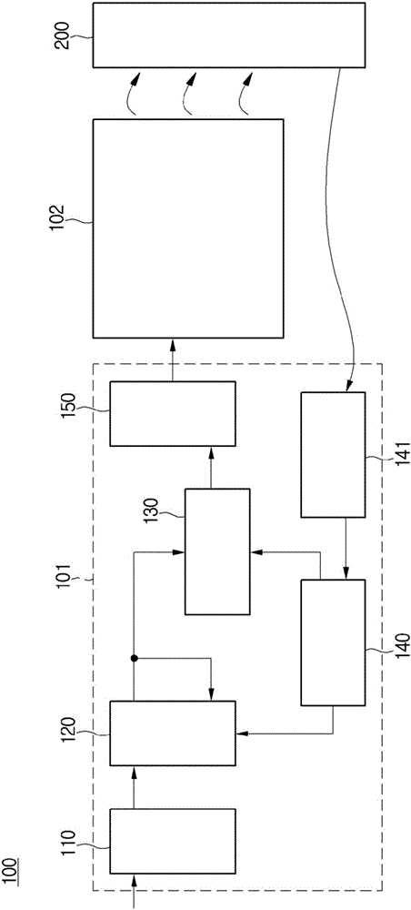
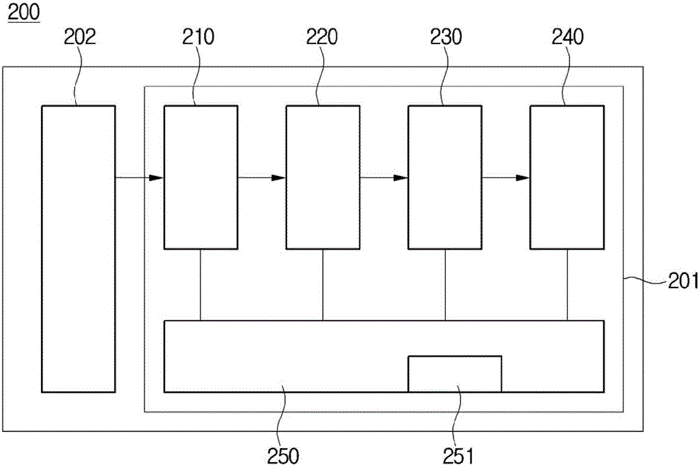
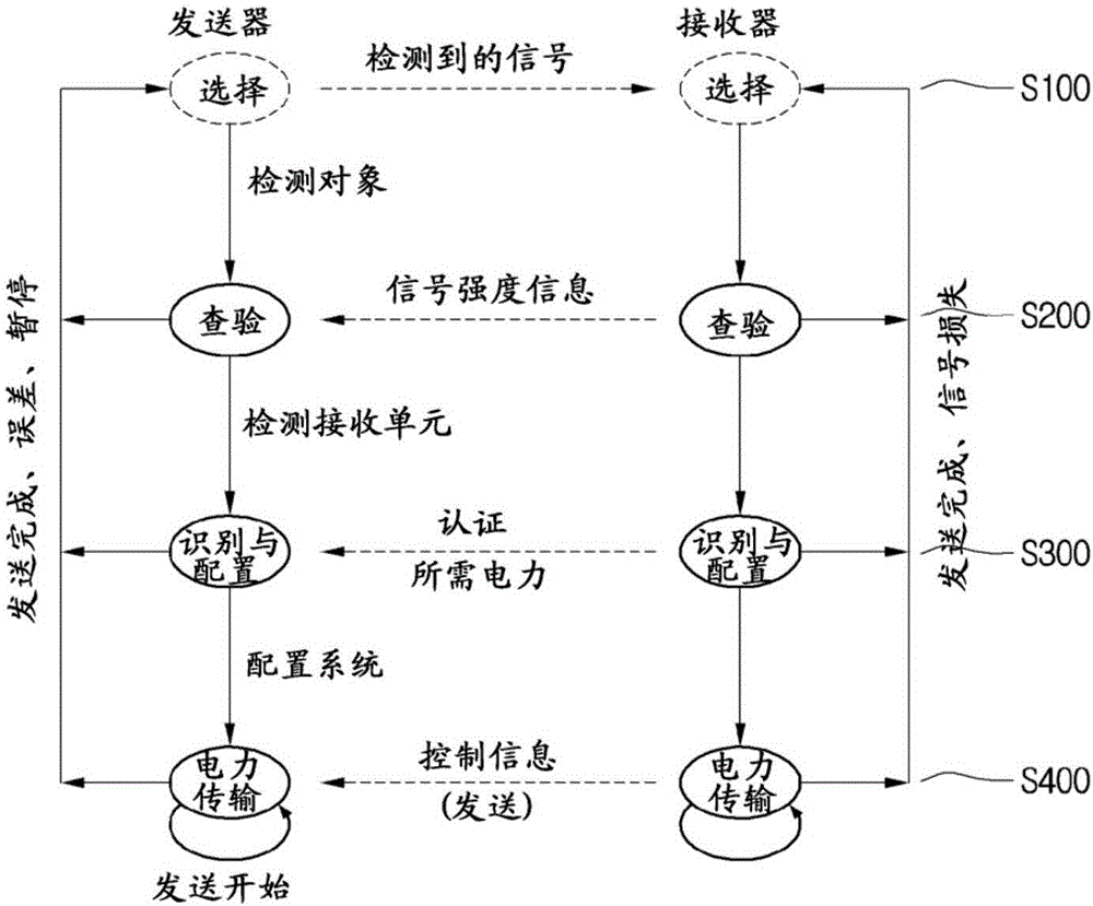
[0044] Hereinafter, a wireless power transmission (WPT) system including a WPT transmitter and a WPT receiver according to an embodiment of the present invention will be described in detail with reference to the accompanying drawings. Various embodiments will now be described more fully with reference to the accompanying drawings in which some embodiments are shown. These inventive concepts may, however, be embodied in different forms and should not be construed as limited to the embodiments set forth herein. Rather, these embodiments are provided so that this disclosure will be thorough and complete, and will fully convey the inventive concept to those skilled in the art. In the drawings, the size and thickness of devices may be exaggerated for convenience. Throughout the specification, like numbers refer to like elements.

[0045] According to the embodiment, various frequency bands from low frequency (50kHz) to high frequency (15MHz) can be selectively used for WPT, and i...


PUM


Abstract

A wireless power transfer and transmission device according to an embodiment of the present invention comprises a transmitting side communication unit, wherein the transmitting side communication unit transmits a first control signal to a receiving side communication unit, receives a second control signal comprising information regarding the amount of power of the first control signal from the receiving side communication unit, and controls the amount of power of the first control signal by comparing, on the basis of the second control signal, the amount of power of the first control signal with a predetermined range.

Description

technical field [0001] Embodiments relate to wireless power transfer systems. Background technique [0002] A wireless power transfer (WPT) system is a technology for transmitting power through space without wires and maximizing convenience of power supply to mobile devices and digital home appliances. [0003] The WPT system has the advantages of saving energy through real-time power usage control, overcoming space limitations of power supplies, using battery recharging to reduce waste battery discharge, and the like. [0004] As methods for realizing the WPT system, there are generally a magnetic induction method and a magnetic resonance method. [0005] The magnetic induction method is a non-contact energy transmission technique in which two coils are brought close to each other so that current is supplied to one coil and electromotive force is generated in the other coil via magnetic flux generated from the current, and this magnetic induction method uses a frequency of...

Claims


Application Information

Patent Timeline
Patent Type & Authority Applications(China)
IPC IPC(8): H02J50/12
CPCH02J50/12H02J50/60H02J50/80H02J7/00045H02J7/00034H02J50/20H04B5/0037H02J7/04
Inventor 李宗宪朴洙永
Owner LG INNOTEK CO LTD
Why Eureka
Try Eureka